
Specifications
| Engine designation | BAS |
| Working volume, cm³ | 4163 |
| Power, kW at rpm | 221/6200 |
| Power, hp at rpm | 300/6200 |
| Maximum torque, Nm at rpm | 380/2600-4700 |
| Cylinder diameter, mm | 84,5 |
| Piston stroke, mm | 92,8 |
| Compression ratio | 11,0 |
| Cylinder firing order | 1-5-4-8-6-3-7-2 |
The Audi Allroad cars also use 8-cylinder petrol engines with two blocks of four cylinders each as a power plant. The cylinder blocks are located at an angle of 90° relative to each other, which is why such engines are designated V8. The cylinder block is made of gray cast iron, and the cylinder head is made of a light metal alloy. The cylinder head is made according to the so-called transverse principle, when the inlet and outlet channels are located diametrically opposite, across the longitudinal axis of the engine. The air-fuel mixture enters from one side of the cylinder head, and the exhaust gases exit on the opposite side, ensuring rapid gas exchange.
Each cylinder of the engine in question has three intake and two exhaust valves. Each cylinder block has two camshafts, which are connected by a drive chain to the corresponding exhaust valve shaft. The camshafts are driven by a chain. In addition, the drive of auxiliary units is also performed by a chain.
The intake and exhaust valves are actuated by the camshaft cams via hydraulic tappets, which automatically adjust the valve clearances and keep them constant. For this reason, valve clearance adjustment is not required during vehicle maintenance.
The crankshaft rotates in five main bearings. The axial clearance of the crankshaft is adjusted by thrust half rings located on the journal of the fourth main bearing (see illustration 1.0). The connecting rods are attached to the crankshaft by means of connecting rod bearings, and to the pistons by means of piston pins. The pistons are made of aluminum alloy and are equipped with three piston rings - two compression rings and one oil scraper ring (see illustration 1.0b).
Crankshaft dimensions
| Main bearing journal diameter, mm | Connecting rod bearing journal diameter, mm | |
| Nominal size | 65,000 | 54,000 |
| Repair size | 64,750 | 53,750 |
The engine has a liquid cooling system. It should be remembered that the engine cooling circuit must be filled with a cooling liquid all year round, which is a mixture of the appropriate concentrate (antifreeze) with anti-corrosion additives and distilled water.
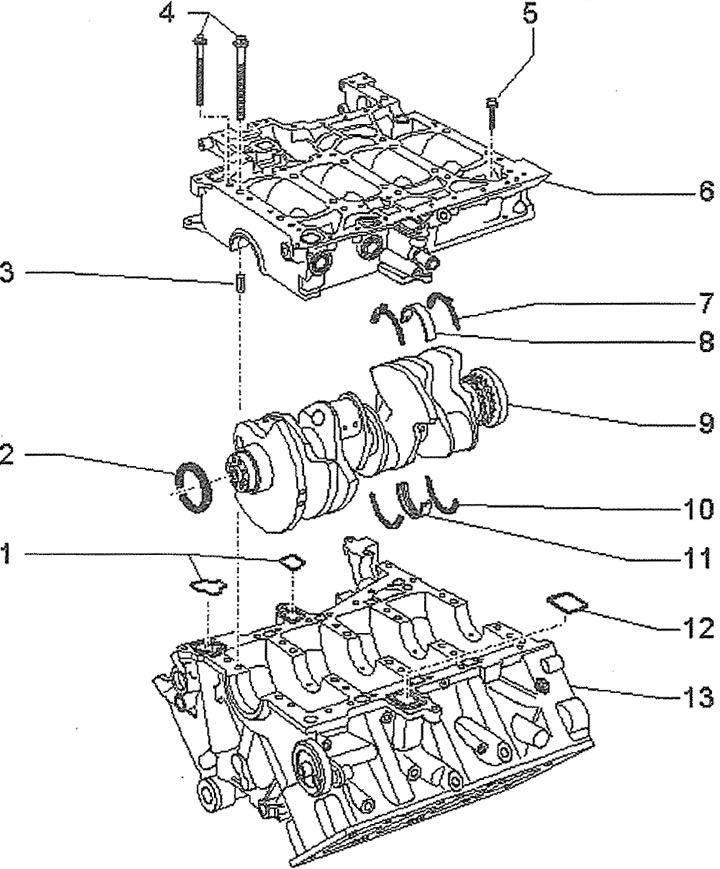
1.0. Crankshaft:
1 - sealing gaskets
2 - crankshaft oil seal
3 - centering sleeve (3 pcs.)
4 - crankshaft bearing housing mounting bolts
5 - crankshaft bearing housing mounting bolt
6 - crankshaft bearing housing
7 - lower thrust half ring
8 - lower main bearing shell
9 - crankshaft
10 - upper thrust half ring
11 - upper main bearing shell
12 - sealing gasket
13 - cylinder block
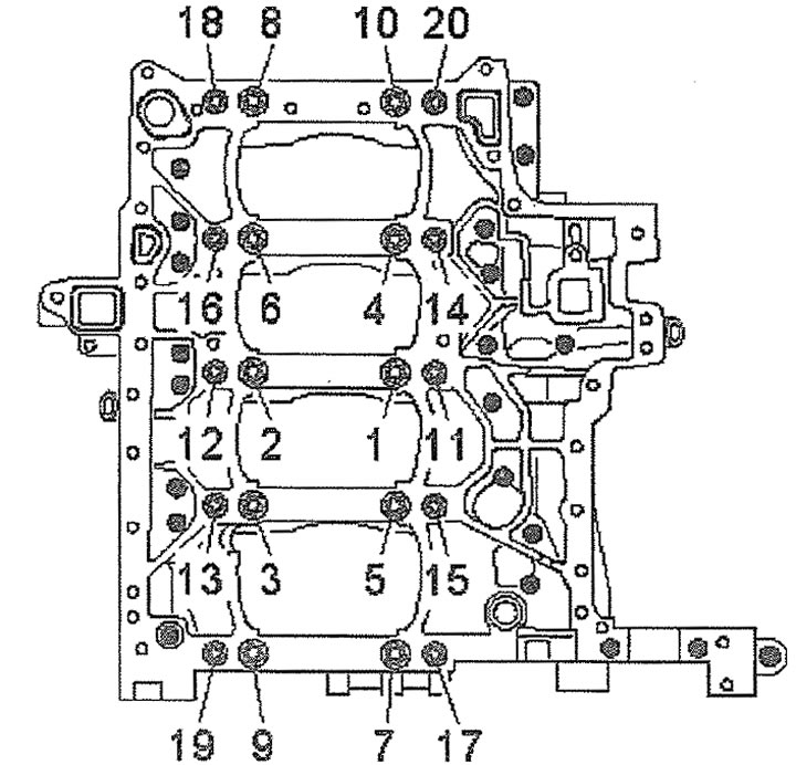
1.0a. Tightening the crankshaft bearing housing mounting bolts:
1st pass - tighten bolts 1-10 to 30 Nm;
2nd pass - tighten bolts 11-20 to 20 Nm;
3rd pass - tighten bolts 1-10 to 50 Nm;
4th pass - tighten bolts 11-20 to 30 Nm;
5th pass - tighten bolts 1-10 by 90°;
6th pass - tighten bolts 11-20 by 90°.
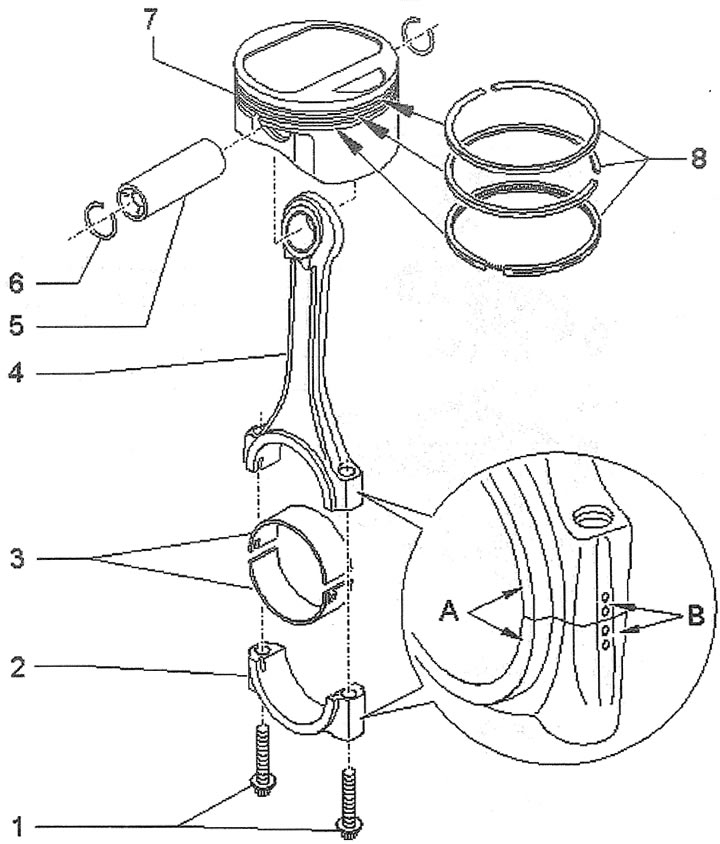
1.0b. Engine piston and connecting rod:
1 - connecting rod cap mounting bolts. Tightening torque: 1st pass - 30 Nm; 2nd pass - turn 90°
2 - connecting rod cap. The caps must not be interchanged. When removing, mark B to indicate that the cap belongs to the cylinder. When installing, observe mounting position A
3 - upper and lower connecting rod bearing shells
4 - connecting rod
5 - piston pin. When assembling the piston and connecting rod, it is recommended to heat the piston to 60'C
6 - piston pin retaining ring
7 - piston
8 - piston rings. The ring locks are located at an angle of 120° relative to each other. When installing, the inscription "TOP" should be facing the piston bottom
[The original text of the material can be found on the website audimanual.ru]