Repair Chevrolet Repair Toyota Repair Honda Repair AvtoVAZ Repair Mercedes-Benz Repair BMW Repair Opel
Home  |  Contacts  |  Sitemap  |    
English Русский
Български
Беларускі
Український
Српски
Hrvatski
Română
Polski
Slovenský
Magyar
AudiManual.ru


  • AUDI 80
  • AUDI 100
  • AUDI A3
  • AUDI A4
  • AUDI A6
  • AUDI A8
  • AUDI Q
  • OTHER
  • ARTICLES
C4 (1990-1994) C4 (1990-1994, petrol) C3 (1982-1990) C3 (1982-1990, petrol) C3 (1982-1990, diesel)

Camshaft drive (Audi 100 C3)

  • Home
  • Audi 100
  • C3 (1982-1990)
  • Power unit
  • Engines 4-cylinder
  • Camshaft drive
            0
Table of contents: Disassembly ↓ Assembly and adjustment ↓

Camshaft Drive Parts


Camshaft Drive Parts

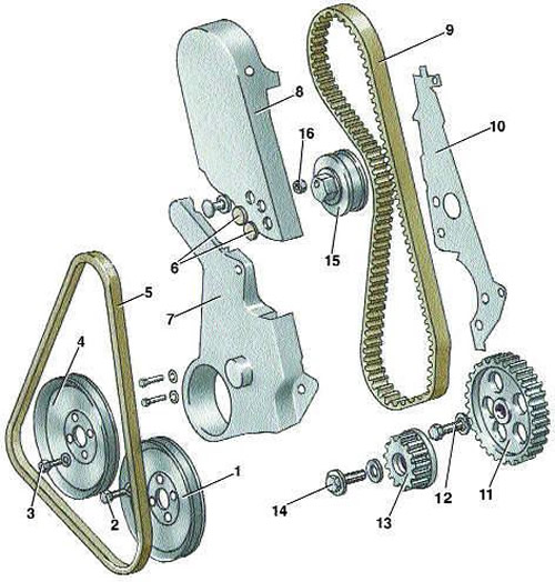
  • 1 - water pump pulley;
  • 2 - water pump pulley mounting bolt;
  • 3 - crankshaft pulley mounting bolt;
  • 4 - crankshaft pulley;
  • 5 - belt;
  • 6 - plugs;
  • 7 - lower camshaft drive cover;
  • 8 - Upper camshaft drive cover;
  • 9 - camshaft drive belt;
  • 10 - rear cover of the camshaft drive;
  • 11 - intermediate shaft gear;
  • 12 - intermediate shaft gear mounting bolt;
  • 13 - crankshaft gear;
  • 14 - crankshaft gear mounting bolt;
  • 15 - camshaft drive belt tensioner;
  • 16 - tensioner mounting nut


Adjusting and checking the tension of the camshaft drive belt


Adjusting and checking the tension of the camshaft drive belt

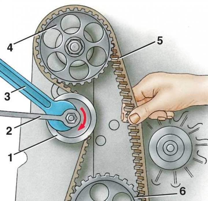
  • 1 - camshaft drive belt tensioner;
  • 2, 3 - spanners;
  • 4 - camshaft toothed wheel;
  • 5 - camshaft drive belt;
  • 6 - intermediate shaft gear


Disassembly


1. Remove the upper camshaft drive cover (see Fig. Camshaft Drive Parts).

2. Loosen the mounting bolts and remove the water pump pulley.

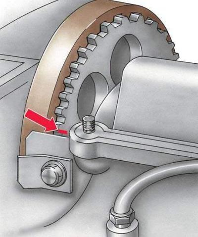
3. Set the piston of the 1st cylinder to TDC of the compression stroke (both valves are closed). The mark on the crankshaft pulley must be aligned with the arrow on the lower camshaft drive cover.

4. Remove the four bolts and crankshaft pulley.

5. Remove the lower camshaft drive cover.

6. Loosen the belt tensioner mounting nut and use a wrench to turn the belt tensioner eccentric shaft counterclockwise to loosen the belt tension.

7. Remove the belt from the crankshaft, camshaft and intermediate shaft gears and from the tensioner mechanism tensioner.

8. Unscrew the nut and remove the tensioner.

9. Loosen the bolt and remove the intermediate shaft gear, remove the key.

10. Loosen the bolt and remove the crankshaft gear, remove the key.

11. Loosen the bolt and remove the toothed wheel from the camshaft, remove the key.

12. Loosen the bolts and remove the rear cover of the camshaft drive.

Assembly and adjustment


1. Install the rear camshaft drive cover and tighten the bolts that secure it.

2. Insert the key into the groove on the crankshaft and install the gear. Apply sealant to the thread of bolt 14, screw in the bolt with the washer and tighten to a torque of 200 N·m (20.0 kgf·m).

2. Insert the key into the groove on the crankshaft and install the gear. Apply sealant to the…


3. Insert the key into the groove on the camshaft, install the toothed wheel, screw in the bolt with the washer and tighten to a torque of 80 N·m (8.0 kgf·m). The mark on the toothed wheel must coincide with the upper plane of the cylinder head cover gasket on the left side of the engine.


4. Insert the key into the groove of the intermediate shaft, install the gear wheel, screw in bolt 12 with a washer and tighten to a torque of 80 N·m (8.0 kgf·m).

5. Install the camshaft drive belt tensioner mechanism.

5. Install the camshaft drive belt tensioner mechanism.


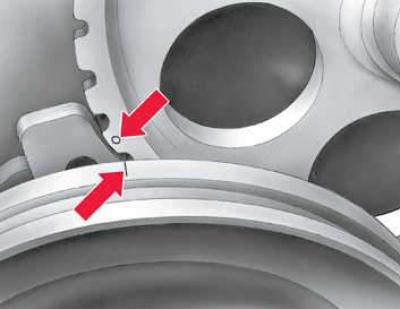
6. Temporarily install pulley 4 of the crankshaft on gear 13. Piston of the 1st cylinder should be at TDC. Turn gear 11 of the intermediate shaft so that the mark on it aligns with the mark on pulley 4 of the crankshaft, as shown in the figure.

7. Put on belt 9.

8. Turn key 3 (see fig. Adjusting and checking the tension of the camshaft drive belt) mechanism 1 of tensioning the belt 5 clockwise to pre-tension the belt. Check that the TDC marks have not moved. Turn mechanism 1 of tensioning further clockwise, tensioning belt 5 so that it can be turned 90°, grasping it with two fingers in the middle between the camshaft and intermediate shaft. Holding the tensioning mechanism with key 3, tighten its fastening nut with key 2.

9. Remove crankshaft pulley 4. Install lower cover 7 of the camshaft drive (see Fig. Camshaft Drive Parts).

10. Install the crankshaft pulley, tighten bolts 3 to a torque of 20 N·m (2.0 kgf·m).


11. Install the water pump pulley.

12. Install the upper camshaft drive cover.

(This publication is borrowed from the resource AudiManual.ru)
The article was checked by auto expert Daniil Ushakov
This article is available at russian, bulgarian, belarusian, ukrainian, serbian, croatian, romanian, polish, slovak, hungarian

Share information:
Previous articles
Audi 100 C3: Engines 4-cylinder
Next articles

Clearances between camshaft lobes and valve lifters
Inspection, defect detection and repair of cylinder head parts
Removal and installation valves (disassembling the cylinder head)
Installing the camshaft and valve lifters
Removal and installation the flywheel
Replacing crankshaft seals
Removal and installation the oil pan
Removal, checking and installation the oil pump


Similar articles on other Audi car models:
Removal and installation the camshaft drive belt Audi 80 B2 (1979-1986)
Checking the condition of the protective covers of the drive… Audi A3 Type 8L (1996-2003)
Camshaft chain drive Audi A4 B8 (2007-2015)
Camshaft Drive Chains — Removal and Installation Audi A6 C5 Allroad (1999-2005)
Checking the drive shaft protective cover Audi A8 D2 (1994-2002)
Removal the camshaft drive chains Audi Q5 Type 8R (2008-2017)
Belt Drive Camshaft — Design Description Audi A2 (1999-2005)
Link to this page in different formats


Visitor comments

No comments yet


How much will 45 + 24 =


100(C4, 1990-1994) 
  • General information
  • User manual
  • Power unit
  • Engine repair
  • Ignition system
  • Fuel system (gasoline)
  • Fuel system (diesel)
  • Lubrication system
  • Cooling system
  • Exhaust system
  • Transmission
  • Clutch
  • Car gearbox
  • Drive shafts
  • Chassis
  • Car suspension
  • Steering
  • Wheels and tires
  • Brake system
  • Body
  • Ventilation and heating
  • Body repair
  • Electrical equipment
  • Power devices
  • Lighting and appliances
  • Electrical circuits
 
100(C4, 1990-1994, petrol) 
  • General information
  • Operation and maintenance
  • Power unit
  • Engine repair
  • Exhaust system
  • Cooling system
  • Supply system
  • Air filter
  • Mono-Motronic injection system
  • Digifant injection system
  • KE-III-Jetronic and KE-Motronic
  • MPI and MPFI injection system
  • Transmission
  • Clutch
  • Car gearbox
  • Chassis
  • Suspension and steering
  • Brake system
  • Wheels and tires
  • Body
  • Exterior
  • Interior
  • Electrical equipment
  • Fuses and relays
  • Power devices
  • Ignition system
  • Lighting and signaling
  • Equipment and devices
  • Electrical circuits
 
100(C3, 1982-1990) 
  • General information
  • User manual
  • Maintenance
  • Specifications
  • Power unit
  • Engines 4-cylinder
  • Engines 5-cylinder
  • Diesel engine
  • Cooling system
  • Power system (carburetor)
  • Power system (injector)
  • Fuel system (diesel)
  • Transistor ignition system
  • Electronic ignition system
  • Transmission
  • Clutch
  • 4 speed gearbox 014
  • 5 speed gearbox 013 and 093
  • 5 speed gearbox 016 and 012
  • Shift mechanism KP 016
  • Automatic transmission
  • Front wheel drive
  • Chassis
  • Front suspension
  • Rear suspension
  • Steering
  • Brake system
  • Body
  • Body elements
  • Electrical equipment
  • Lighting and appliances
  • Power devices
  • Electrical circuits
 
100(C3, 1982-1990, petrol) 
  • General information
  • Maintenance and operation
  • 4 cylinder engine
  • Engine repair
  • Cooling and lubrication system
  • Supply system
  • Ignition system
  • 5 cylinder engine
  • Engine repair
  • Cooling and lubrication system
  • Supply system
  • Ignition system
  • Transmission
  • Clutch and drive shafts
  • 4 speed gearbox 014
  • 5 speed gearbox 013 and 093
  • 5 speed gearbox 016 and 012
  • Automatic gearbox
  • Chassis
  • Steering
  • Front suspension
  • Rear suspension
  • Brake system
  • Body
  • Body elements
  • Doors, locks and windows
  • Body repair
  • Electrical equipment
  • Equipment and devices
  • Power devices
  • Electrical circuits
 
100(C3, 1982-1990, diesel) 
  • General information
  • User manual
  • Maintenance
  • Troubleshooting
  • Power unit
  • Engine in a car
  • Engine removed
  • Cooling system
  • Fuel system
  • Exhaust system
  • Starting and charging
  • Preheating
  • Transmission
  • Clutch
  • Mechanical gearbox
  • Automatic gearbox
  • Drive shafts
  • Chassis
  • Brake system
  • Suspension
  • Steering
  • Body
  • Exterior
  • Interior
  • Electrical equipment
  • Equipment and devices
  • Electrical circuits
 
AudiManual.ru © 2017-2026 · Mobile version · Feedback · Sitemap: EN BG BY UA RS HR RO PL SK HU · Site search · News and articles
80 B2 · 80 B3 petrol · 80 B3 · 80 B4 · 100 C3 diesel · 100 C3 petrol · 100 C3 · 100 C4 petrol · 100 C4 · A3 Type 8L · A4 B5 petrol · A4 B5 · A4 B6 petrol · A4 B6 · A4 B7 · A4 B8 · A6 C4 · A6 C5 · A6 C5 Allroad · A8 D2 · Q5 Type 8R · Q7 Typ 4L · Audi A2 ·
This site uses cookies 🍪. Click the button to accept this fact.