
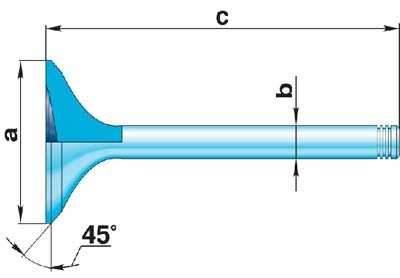
Four-cylinder engine valve dimensions
| inlet valve | exhaust valve | |
|
a
|
40.0 mm
|
33.0 mm
|
|
b
|
7.97 mm
|
7.95 mm
|
|
with
|
91 mm
|
90.8 mm
|
Valve seat dimensions
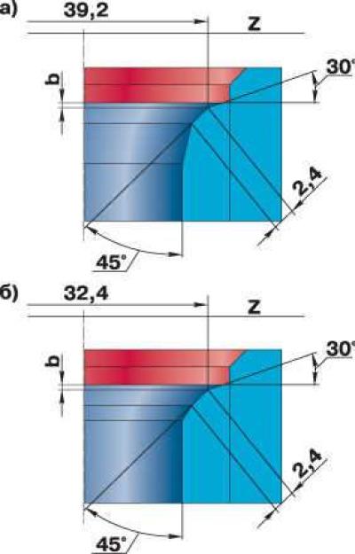
Valve seat dimensions:
- a) inlet valve
- b) exhaust valve
Execution order
1. After disassembling the cylinder head, wash all parts in gasoline, wipe and dry. Clean the combustion chambers and valves from carbon deposits.
2. Inspect the cylinder head. If there are cracks on the combustion chamber walls, traces of burnout, etc., replace the cylinder head.
3. Use a metal ruler and feeler gauges to check whether the flatness of the cylinder head surface adjacent to the block is violated. To do this, place the ruler with its edge on the surface of the cylinder head in the middle, lengthwise and then crosswise, and use a feeler gauge to measure the gap between the surface of the head and the ruler. If the gap exceeds 0.1 mm, replace or grind the head. The minimum permissible height of the head is 132.75 mm. If the height of the head is less after grinding, the head must be replaced.
4. Check the head for cracks by connecting a compressed air hose to one of the cooling jacket holes. Plug all the holes in the head with wooden plugs. Place the head in a bath of water and supply compressed air at a pressure of 1.5 atm. Air bubbles will come out in places where there are cracks.
5. Inspect the valves. If cracks, warping of the valve head, burnout, or deformation of the stem are detected on the working face of the valve, the valve must be replaced.
6. Minor scratches and marks on the valve working face can be removed by lapping. The valve should be lapped to the seat as follows:
- insert the valve into the cylinder head;
- place a valve grinding tool on the valve stem;
- apply a thin layer of lapping paste to the working chamfer of the valve;
- turn the valve with the device in both directions, periodically pressing it against the seat. An external sign of satisfactory lapping is a uniform matte-gray color of the working chamfer and the valve.
7. After lapping, thoroughly rinse the seat and valve and wipe thoroughly with a clean cloth to remove any remaining lapping paste.
8. To check the tightness of the valve, install it in the cylinder head together with the springs and crackers. Then lay the cylinder head on its side and pour kerosene into the channel closed by the valve. If kerosene does not leak into the combustion chamber within 3 minutes, the valve is considered tight. The valve dimensions are shown in Fig. Four-cylinder engine valve dimensions.
9. Check the condition of the valve springs. Replace warped, cracked or broken springs.
10. Check the condition of the valve seats. There should be no signs of wear, cavities, corrosion, etc. on the working chamfers of the seats. Minor damage (minor scratches, marks, etc.) can be removed by grinding the valves. More significant defects are eliminated by grinding. When grinding, the seat dimensions indicated in Fig. should be maintained. Valve seat dimensions.
11. After grinding, grind the valves. Then thoroughly clean and blow out the cylinder head with compressed air so that there are no abrasive particles left in the channels closed by the valves and in the combustion chambers.
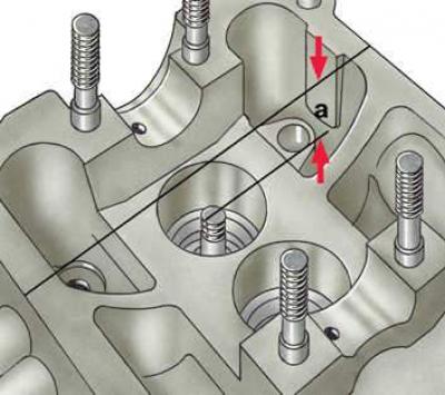
12. It should be taken into account that after grinding the seat, the valve sits deeper in the seat. Therefore, on engines with hydraulic valve lifters, after grinding, it is necessary to measure the distance a between the end of the valve stem pressed against the seat and the upper plane of the cylinder head. If this dimension is less than 33.8 mm for intake valves and less than 34.1 mm for exhaust valves, the cylinder head should be replaced, since in this case the normal operation of the hydraulic valve lifters is disrupted. Thus, the reduction in the working chamfer of the valve seat should not be greater than the difference between the dimension a before grinding and the minimum permissible dimension a.
13. Check the clearances between the guide bushings and the valves. To do this, insert the valve into the guide bushing so that the end of the valve stem is flush with the end of the guide bushing.
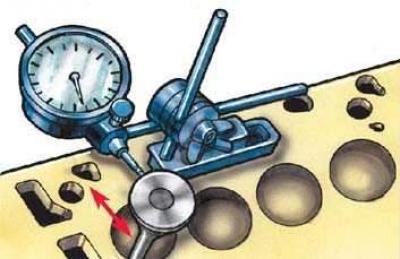
14. Install the indicator leg to the valve head. Measure the clearance by moving the valve from stop to stop in the horizontal plane. If the inlet valve movement exceeds 1.0 mm and the outlet valve movement exceeds 1.3 mm, replace the bushings and valves. The diameters of the inlet and outlet valve stems are different, so you need to check the inlet valve bushings by inserting the inlet valve, and the outlet valve bushings by inserting the outlet valve.
The text is based on materials from the website audimanual