
Camshaft chain drive
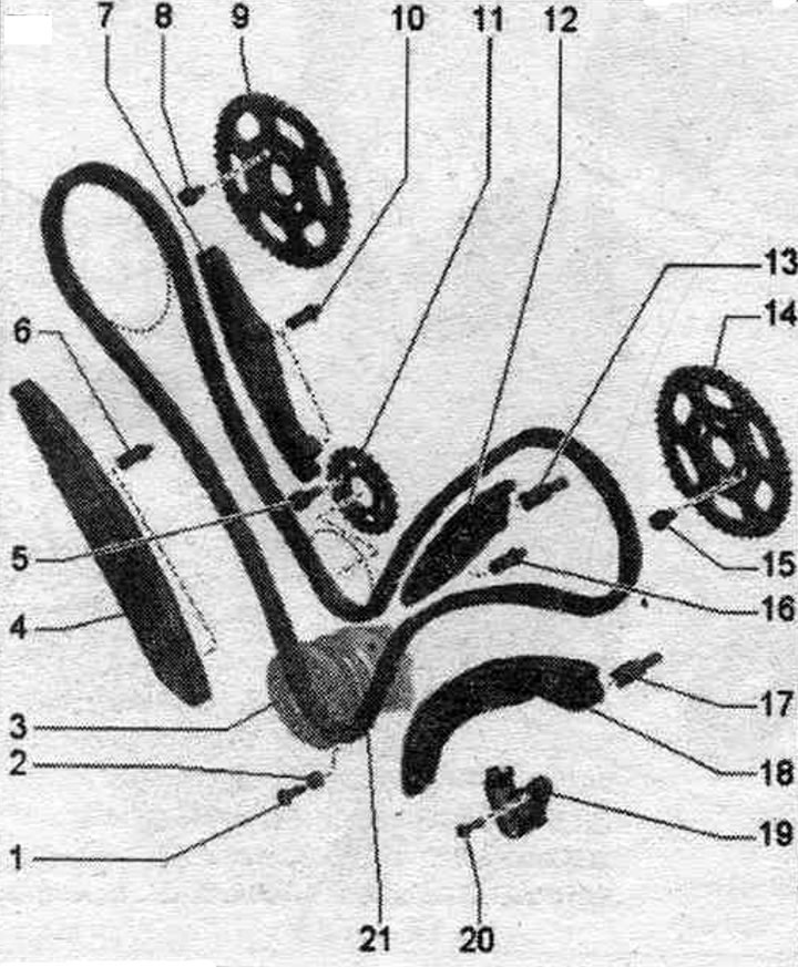
1. Bolt: 9 Nm.
2. Protection against jumping.
3. Crankshaft: with camshaft drive chain sprocket.
4. Stabilizer bar: install in the proper position.
5. Bolt.
6. Guide bolt of the damper; replace; 5 Nm + turn further by 90°.
7. Stabilizer bar: install in the proper position.
8..Bolt: 23 Nm.
9. Intake camshaft timing chain sprocket; mounting position: the side with the inscription is visible from below.
10. Guide bolt of the damper: replace; 5 Nm + turn further by 90°.
11. Sprocket: for balance shaft.
12. Stabilizer bar: install in the proper position.
13. Guide bolt of the damper: 23 Nm.
14. Intake camshaft timing chain sprocket; mounting position: the side with the inscription is visible from below.
15. Bolt: 23 Nm.
16. Guide bolt of the damper: replace; 5 Nm + turn further by 90°.
17. Tension bar guide bolt: 23 Nm.
18. Tensioner bar.
19. Timing chain tensioner.
20. Bolt: replace; 5 Nm + turn further by 90°.
21. Camshaft chain: remove the chain from the camshafts; before removing, mark the direction of movement with paint.
Removal the chain from the camshafts
The engine and gearbox are installed. If work is being performed only on the cylinder head of the first bank of cylinders (on the right), do not remove the timing chain cover on the cylinder head of the second bank of cylinders (on the left). Remove the upper timing chain covers. Insert the guide pins of the adapter "T40058" as shown below: the large diameter "arrow 1" faces the engine, the small diameter "arrow 2" faces the adapter. Risk of damage due to jumping of the camshaft drive chain. Turn the crankshaft only in the direction of engine rotation "arrow".
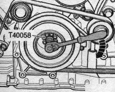
Rotate the crankshaft using the T40058 adapter until the vibration damper is at the TDC mark. The glued "arrow" marking is vertically at the top.
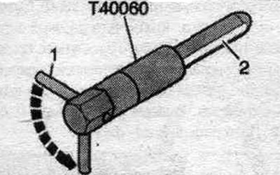
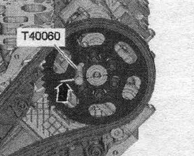
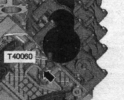
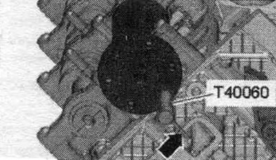
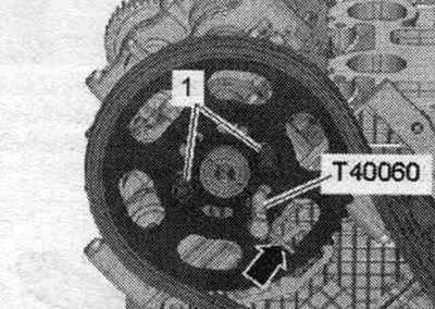
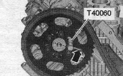
The "T40060" locating pin has a "2" chamfer, which facilitates its installation with a slight shift in the camshaft and cylinder head fixing holes. First, insert the adjusting pin so that pin "1" is perpendicular to the camshaft axis. For correct installation at "TDC", it is necessary to turn pin "1" by 90°"arrow" so that it is vertical in relation to the camshaft axis.
Make sure that the camshafts of both cylinder heads are in the "TDC" position: the camshafts should be secured with "T40060" pins, the "arrow" pin in the "T40060" installation pin should be positioned perpendicular to the axis of symmetry of the camshaft at cylinder bank 1 (right).
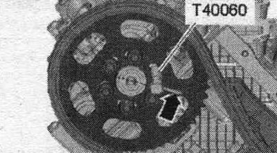
The "arrow" pin in the "T40060" installation pin must be positioned perpendicular to the axis of symmetry of the camshaft at cylinder bank 2 (left).
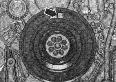
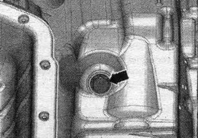
Unscrew the screw plug "arrow" on the top of the oil. pallet.
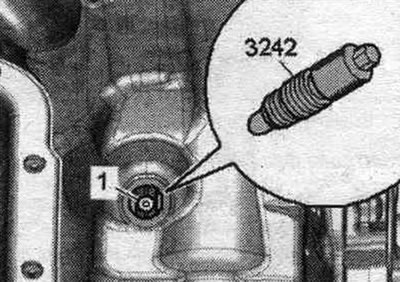
Screw the fixing bolt "3242" into the hole with a torque of 20 Nm, if necessary, slightly turn the crankshaft in both directions to fully center the bolt.
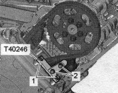
Secure the support "T40246" as shown in the figure.
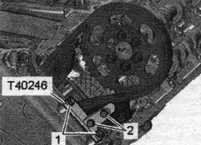
| Step | Screws | Tightening torque |
| 1 | "1" M6x40 | screw it in by hand until it stops |
| 2 | "2, 3" M6x20 | screw it in by hand until it stops |
| 3 | "2" M6x40 | 8 Nm |
| 4 | "1, 3" M6x20 | 8 Nm |
Remove the dowel pin "T40060" from both camshafts. Loosen the arrow bolts.
Loosen the arrow bolts. Remove the camshaft sprockets and timing chains.
Install
Crankshaft "1" is locked in the "TDC" position using locking screw "3242." Replace any bolts that were overtightened. Replace the seal. the ring of the threaded plug marks the "TDC" mark. Ensure that the camshafts of both cylinder heads are at the "TDC" position. The camshafts should be secured with "T40060" pins. The "arrow" pin in the "T40060" locating pin should be positioned perpendicular to the axis of symmetry of the camshaft on cylinder bank 1 (right).
The "arrow" pin in the "T40060" installation pin must be positioned perpendicular to the axis of symmetry of the camshaft at cylinder bank 2 (left).
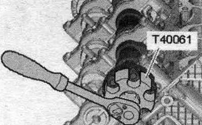
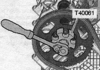
Remove the dowel pin "T40060" from both camshafts. When turning the camshaft, none of the crankshaft pistons should be at TDC. If the camshafts are not locked, their position can be slightly adjusted using the T40061 adapter. To do this, screw the chain sprocket bolts into the camshaft.
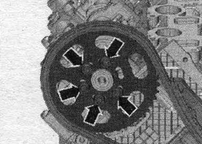
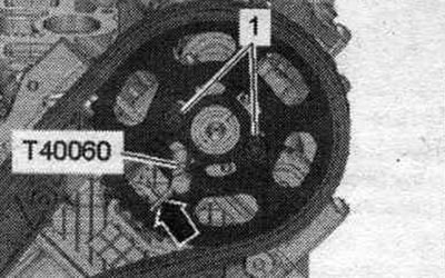
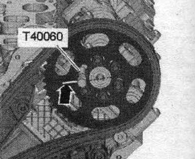
Install the left camshaft chain sprocket with the camshaft chain. The threaded holes of the camshaft must be located in the middle of the elongated holes of the camshaft sprocket. Then tighten 2 bolts "1" of the camshaft sprocket. The sprocket should rotate on the camshaft, but should not be warped. Secure the left camshaft with the T40060 locating pin. The "arrow" pin in the T40060 locating pin must be positioned parallel to the camshaft timing chain axis of symmetry.
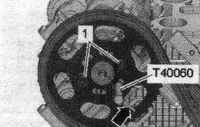
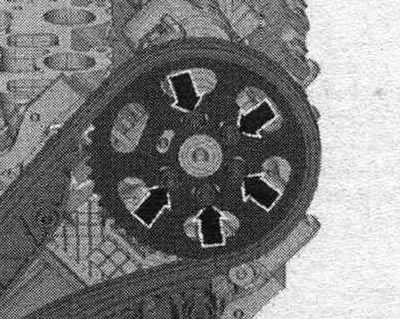
Install the right camshaft chain sprocket with the camshaft chain. The threaded holes of the camshaft must be located in the middle of the elongated holes of the camshaft sprocket. Then tighten 2 bolts "1" of the camshaft sprocket. The sprocket should rotate on the camshaft, but should not be warped. Secure the right camshaft with the T40060 locating pin. The "arrow" pin in the T40060 locating pin must be positioned parallel to the camshaft timing chain axis of symmetry.
Remove support "T40246".
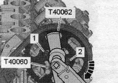
Using a 2nd mechanic: tighten the right camshaft timing chain sprocket with the "T40062" adapter and a torque of 20 Nm clockwise "arrow" and maintain the pre-tension. Tighten bolts "1" and "2" of the right camshaft sprocket.
Next, maintain the pre-tension and tighten bolts "1" of the left camshaft chain sprocket. Remove the "T40062" adapters and "T40060" dowel pins. Tighten the remaining left and right camshaft sprocket bolts.
Unscrew the fixing bolt "3242".
Timing phase control
Risk of damage due to jumping of the camshaft drive chain. Turn the crankshaft only in the direction of engine rotation "arrow". Turn the crankshaft 2 turns until it is before "TDC". Fix crankshaft "1" from turning with locking bolt "3242" with a torque of 20 Nm. Possibility of incorrect adjustment due to inaccurate position of "TDC". If the shaft has passed the "TDC" mark: Turn the crankshaft 2 turns until the crankshaft is again before "TDC". Then lock the crankshaft with locking bolt "3242" with a rotational movement. Make sure that the camshafts of both cylinder heads are in the "TDC" position. The camshafts should be fixed with pins "T40060". The pin "arrow" in the locating pin "T40060" must be located perpendicular to the axis of symmetry of the camshaft at cylinder bank 1 (right).
The "arrow" pin in the "T40060" installation pin must be positioned perpendicular to the axis of symmetry of the camshaft at cylinder bank 2 (left).
Timing phase adjustment
If one of the camshafts cannot be locked, loosen all the arrow bolts of the corresponding camshaft by approximately 1 turn.
Install the adapter "T40061" on the heads of the loose bolts. Turn the camshaft using the adapter "T40061" at a small angle in both directions until the adjusting pin "T40060" enters into place. The "arrow" pin in the "T40060" installation pin must be positioned parallel to the axis of symmetry of the camshaft chain transmission. Tighten the camshaft sprocket bolts with the "T40061" adapter still installed and the "T40060" adjusting pin inserted to a torque of approximately 5 Nm. Remove the "T40060" adjusting pin and the "T40061" adapter. Tighten the camshaft sprocket bolts to the final torque. If necessary, repeat the process on another row of cylinders. Loosen the locking bolt "3242". Repeat the timing phase check.
Installation is in reverse order, install the upper drive chain covers.
(The text is based on materials from the website audimanual)