
Crankshaft
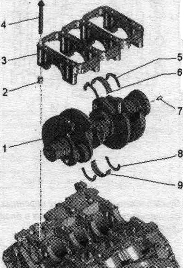
1. Crankshaft.
2. Guide bushing: 4 pcs.; insert into the cylinder block.
3. Camshaft frame.
4. Bolt: replace.
5. Crankshaft axial locking liner: only on main bearing 3; mounting position: lubrication grooves facing outward; monitor the fixation.
6. Bearing insert: for camshaft frame without oil groove; replace old bearing shells; install new crankshaft frame bearing shells with the correct color markings.
7. Dowel pin: check for secure fit in the crankshaft.
8. Crankshaft axial locking liner: only on main bearing 3; mounting position: lubrication grooves facing outward.
9. Bearing insert: for cylinder block with oil groove; replace old bearing shells; install new bearing shells with the correct color markings.
Crankshaft frame - last and bolt tightening torque
Replace bolts that were tightened with additional tightening. Install both mounting bushings into the cylinder block. Tighten the bolts in 3 phases in the specified sequence.
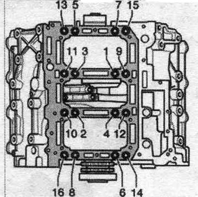
| Step | Screws | Tightening torque/rotation angle |
| 1 | "1...16" | 30 Nm |
| 2 | "1...16" | 50 Nm |
| 3 | "1...16" | turn 180° |
Accessories for main bearing shells installed in the cylinder block
At the factory, bearing liners of the correct thickness are installed in the cylinder block. Colored dots on the bearing shell are used to mark the thickness of the bearing shells.
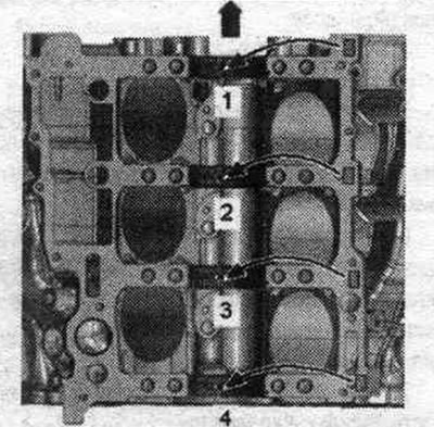
"Arrow". Belt pulley side.
The belonging of the bearing shells to the cylinder block is indicated by a letter next to the corresponding bearing.
| Letter on the cylinder block | Bearing color |
| R = | red |
| G = | yellow |
| B = | blue |
Matching the crankshaft bearing shells to the crankshaft frame
At the factory, bearing shells of the correct thickness are installed in the camshaft frame. Colored dots on the bearing shell are used to mark the thickness of the bearing shells. The assignment of the bearing shells to the camshaft frame is indicated on the crankshaft flywheel flange by a series of letters. The first letter in the row is for bearing "1", the second letter is for bearing "2", and so on.
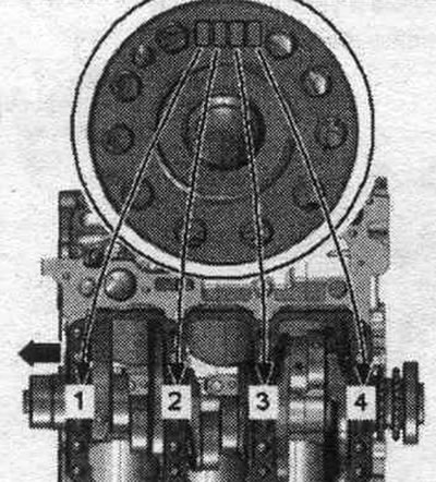
| Letter on the crankshaft | Bearing color |
| R = | red |
| G = | yellow |
| B = | blue |
Position of centering bushings
Check whether the centering bushings "1...4" are installed in their places in the camshaft frame, as shown in the figure.
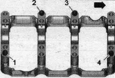
"Arrow". Belt pulley side.