
Table of contents: Pistons and connecting rods ↓ Mounting position of pistons ↓
Pistons and connecting rods
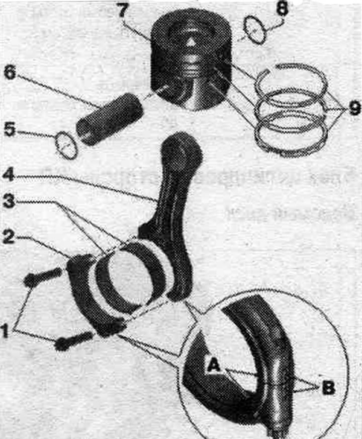
1. Screws: replace; lubricate the threads and mating surface with oil; 35 Nm + turn further by 90°.
2. Connecting rod cap: thanks to the connecting rods made using the constructive fracture (cracking) method, the connecting rod cap is installed in only one position and only on the corresponding connecting rod; mark for reinstallation; mark the cylinder affiliation with paint "B"; when installing, please note: the wide adjusting flange "A" must be directed in the same direction on both the connecting rod and the connecting rod cap.
3. Bearing shells: install in the proper position; replace old bearing shells; take into account the design: upper liner (facing the piston) made of more wear-resistant material; a distinctive feature on new bearing shells: a black stripe on the working surface, at the edge of the joint; make sure the locking tabs are securely seated.
4. Connecting rod: with a broken cover; mark the cylinder affiliation with paint "B"; axial clearance for each new connecting rod pair: 0.20...0.44 mm; replace only the entire set; when installing, please note: the wide adjusting flange "A" must be directed in the same direction on both the connecting rod and the connecting rod cap.
5. Retaining ring: replace.
6. Piston pin.
7. Piston: measure piston protrusion at "TDC"; mark mont. position and belonging to the cylinder; if a scratch appears on the piston bottom or piston skirt, replace the piston.
8. Retaining ring: replace.
9. Piston rings: measure the thermal clearance; remove and install using piston ring pliers; installation position: "TOP" mark or inscription - to the piston bottom; spread the locks around the circumference at 120°.
Piston cooling oil nozzle
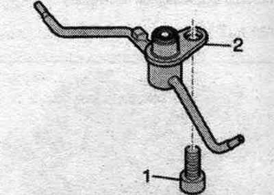
1. Bolt - 9 Nm. 2. Piston cooling oil nozzle with valve. Risk of damage to oil injectors. Do not bend the oil nozzles. Check the oil jet clearance after reinstalling the pistons. Bent oil injection nozzles must be replaced.
Mounting position of pistons
Risk of damage to the piston crown. To correctly install already used pistons, mark the piston to cylinder alignment on the piston bottom using paint. Do not score the piston crown with a center punch, scraper, notch or similar tool.
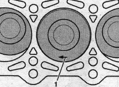
The installation position of the arrow "pos. 1" on the piston bottom points towards the belt pulleys.
Mark the connecting rods
Before removing the connecting rods and connecting rod bearing caps, mark their alignment with an "arrow" using a felt-tip pen.
The connecting rod must be replaced as an assembly only. It is prohibited to swap connecting rod bearings.
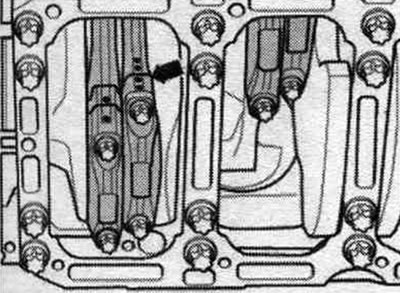
Mounting position of connecting rods
The larger shoulder of the connecting rods "arrows" faces the adjacent main bearing.
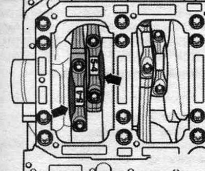
The figure shows the front pair of pistons.