
Table of contents: Timing chain covers ↓ Removal and installation the lower… ↓
Timing chain covers
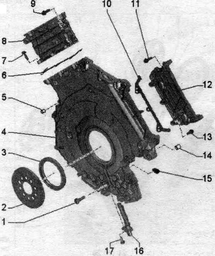
1. Bolt: replace.
2. Engine speed sensor ring gear "G28".
3. Shaft seal: for crankshaft on gearbox side.
4. Lower drive chain cover.
5. Guide sleeve.
6. Gasket: replace.
7. Bolt: replace.
8. Left drive chain cover.
9. Bolt: replace.
10. Gasket: replace.
11. Bolt: replace.
12. Right drive chain cover.
13. Bolt: replace.
14. Guide sleeve.
15. Sealing element: 2 pcs.
16. Engine speed sensor "G28".
17. Bolt.
Upper timing chain covers - sequence and tightening torque
Replace bolts that were tightened with additional tightening. Tighten the bolts in 4 phases in the specified sequence.
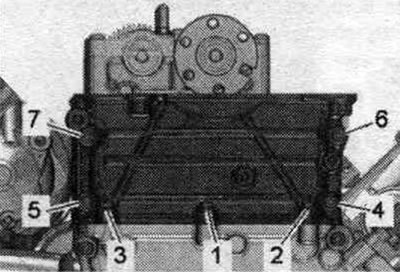
| Step | Screws | Tightening torque/rotation angle |
| 1 | "1, 2, 3" | screw it in by hand until it stops |
| 2 | "4...7" | screw it in by hand until it stops |
| 3 | "1...7" | 8 Nm |
| 4 | "1...7" | 8 Nm, 90° turn |
Lower timing chain cover - last and tightening torque
Replace bolts that were tightened with additional tightening. Tighten the bolts in 5 stages as follows.
Stage 1, 2
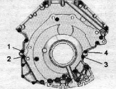
| Step | Screws | Tightening torque |
| 1 | Install the lower timing chain cover with sealant and gaskets onto the cylinder block | |
| 2 | "1, 2, 3, 4" | Tighten steel bolts M6x20 to a torque of 9 Nm |
Tighten the bolts in 10 steps in the sequence shown.
Stage 3...5
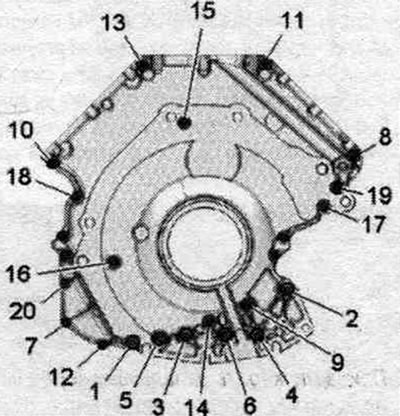
| Step | Screws | Tightening torque/rotation angle |
| 3 | "1...20" | 3 Nm |
| 4 | "1...20" | 3 Nm - these measures also take into account the fit of the lower timing chain cover |
| 5 | "1...20" | Turn 90° further |
Removal and installation the upper timing chain cover
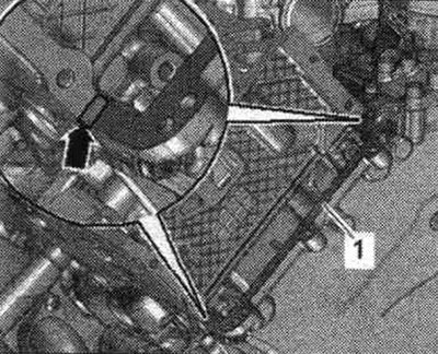
Left upper timing chain cover: Remove the diesel particulate filter: Remove the left cylinder head cover. If present, unscrew bolts "2" and remove the heat shield. "Pos. 1" should not be taken into account.
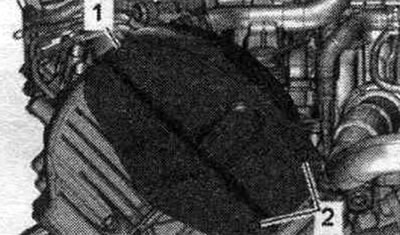
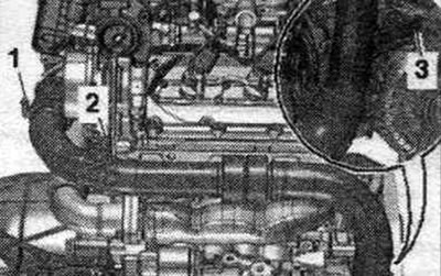
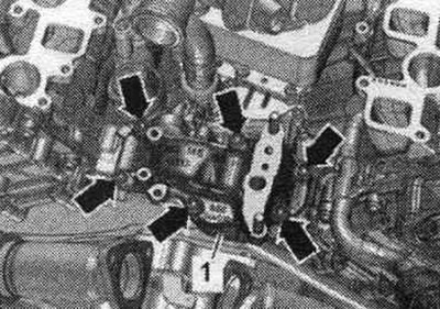
Right Upper Drive Chain Cover: Remove the front wall of the water drain box. Remove the right cylinder head cover. Unscrew bolts "2, 3". Remove the air duct hose by loosening the hose clamp "1". Press the air duct pipe back.
All
Loosen the nuts in sequence. "7...1". Carefully separate and remove the top cover of the drive chain from the gluing area.
Install
Remove any remaining sealant from the gasket. timing chain cover flanges. Remove any remaining sealant from the timing chain cover and cylinder head, for example, using a rotating brush with plastic bristles. Clean the sealing surfaces from oil and grease. Cut off the tube tip along the front mark (opening diameter approx. 1.5 mm). Install gasket "1". Apply sealant "arrow" to the transitions between the cylinder head and the lower timing chain cover, as shown in the figure. Danger of blockage of system channels. lubrication when there is excess sealant. The sealant bead should not be thicker than the specified size. The bead of sealant should protrude above the seating surface by 1.5...2.0 mm.
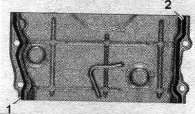
Apply beads of sealant "1, 2" to the clean seating surface of the left timing chain cover as shown in the figure.
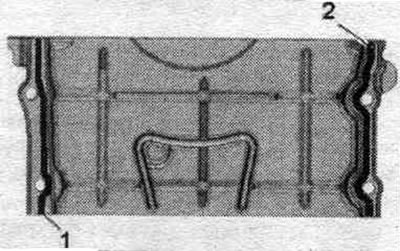
Apply beads of sealant "1, 2" to the clean seating surface of the right timing chain cover as shown in the figure. Install timing chain covers within 5 minutes after applying sealant. Insert the timing chain cover and tighten the bolts.
Installation in reverse order.
Left Upper Timing Chain Cover: Install the left cylinder head cover. Install the diesel particulate filter.
Right Upper Timing Chain Cover: Install the air duct tube. Install the right cylinder head cover. Install the front wall of the water drain box.
Removal and installation the lower timing chain cover
The gearbox is removed. Remove the driven disk. Remove the turbocharger. Remove the upper timing chain covers. Unscrew the "arrow" bolts and move the turbocharger bracket "1" to the side.
Loosen and remove the bolts in sequence. "24...1". Carefully separate and remove the lower drive chain covers from the bonding area. Press the crankshaft seal from the gearbox side out of the lower timing chain cover.
Install
Remove old sealant from the drive chain cover grooves and from the mating surface. Remove any remaining sealant from the lower timing chain cover and cylinder block, for example, with a rotating brush attachment with plastic bristles. Clean the sealing surfaces from oil and grease. Before assembling the gearbox, be sure to clean the threaded holes for securing the power unit in the cylinder block with a tap. Cut off the tube tip at the front mark (hole diameter approx. 1.5 mm). Install the "arrow" seals. Apply beads of sealant "1, 2, 4" to the clean seating surface of the lower drive chain cover, as shown in the figure. The grooves of the seating surfaces must be filled with sealant. The sealant bead should extend 1.5–2.0 mm above the mounting surface. The sealant bead around holes "3" and "5" should be 1.5–2.0 mm thick.
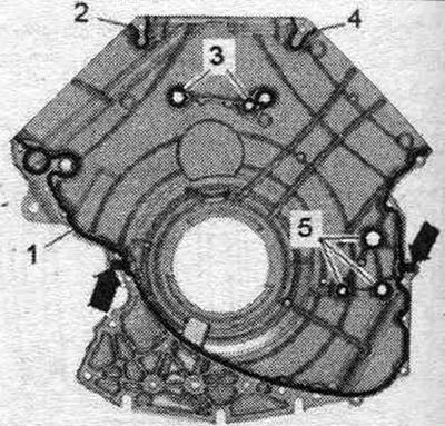
Install the timing chain cover within 5 minutes after applying the sealant. Check that the 2 relief bushings in the cyl. block are in place and install them if necessary. Install the left timing chain cover and tighten the bolts. Installation in reverse order. Install the crankshaft oil seal from the gearbox side. Install the upper timing chain covers. Install the turbocharger bracket. Install the turbocharger. Install the slave disk. Be sure to clean the threaded holes for fixing the power unit in the cylinder block with a tap before assembling the gearbox.