
Table of contents: Mounting position of bearing shells… ↓ Disconnecting the new connecting rod ↓ Oil nozzle and pressure reducing… ↓
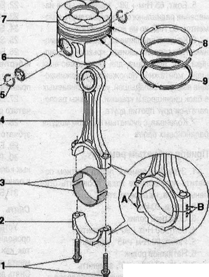
Pistons and connecting rods 1. Bolt, replace, lubricate the thread and mating surface with oil, 30 Nm + 90°, to measure the radial runout, tighten the old bolts to 30 Nm, but do not tighten further; 2. Connecting rod cap, due to the connecting rods made by the method of constructive fracture (cracking), the connecting rod cap is installed only in one position and only on the corresponding connecting rod, mark the correspondence to the cylinder with a colored pencil "B", installation position: marks "A" should be facing the pulleys; 3. Bearing insert, mark previously used inserts, but not on the working surface, upper and lower inserts are not interchangeable: upper (facing the piston) made of more wear-resistant material. Distinctive feature of the new insert: black line on the working surface in the separation area, check the reliability of the fastening, the maximum value of axial play: 0.37 mm; 4. Connecting rod, replace only the entire set, with a broken connecting rod bearing cap, mark the correspondence to the cylinder with a colored pencil "B", installation position: marks "A" should be facing the pulley (to the crankshaft nose); 5. Retaining ring, replace; 6. Piston pin, if the pin enters with difficulty, heat the piston to 60°C; 7. Piston, with combustion chamber, the image does not correspond to the version in the car. Mark the installation position and belonging to the cylinder; 8. Piston rings, compression rings, place locks with a 120° offset, installation position: when installing, the "TOP" marking, or the side with the inscription should face the piston bottom; 9. Piston ring, oil scraper ring, move the joint by 120° to the lower compression ring
Mounting position of bearing shells in connecting rods
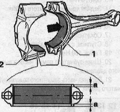
- 1. Bearing insert with oil hole "arrow" for connecting rod
- 2. Bearing insert without lubrication hole of connecting rod bearing cap
Install bearing shells into connecting rod or connecting rod bearing cap in the center. Dimension "a" on the left = dimension "a" on the right.
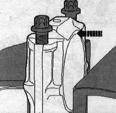
Disconnecting the new connecting rod
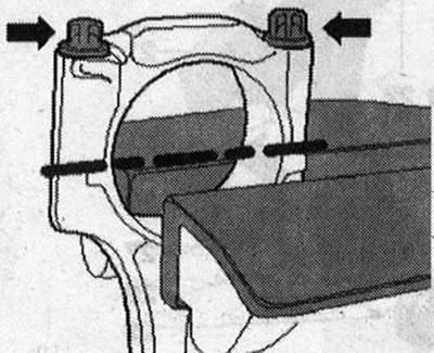
It may turn out that the fracture of new connecting rods at the point of forced fracture is not complete. If the connecting rod bearing cap cannot be removed by hand, do the following: To prevent damage, lightly clamp the connecting rod in a vice with protective jaws, as shown in Fig. Clamp the connecting rod under the stroke "line" it. Unscrew the bolts "arrow" by about 5 turns. With a plastic mallet, carefully hit the connecting rod bearing cap "arrow" until it loosens.
Oil nozzle and pressure reducing valve
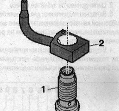
- 1. Bolt with pressure reducing valve, 27 Nm
- 2. Oil nozzle (for cooling pistons)
Installation position: Center the centering edge of the injector in relation to the machined surface of the cylinder block. Do not bend the oil spray nozzles. Bent oil spray nozzles must be replaced.