
Table of contents: Removal ↓ Examination ↓
Removal
1. As described in part A or B this chapter, remove the cylinder head, flywheel, oil pan and baffle plate, oil pump and oil receiver.
2. Inspect the upper parts of the cylinders; possible protrusions from wear must be removed to avoid damaging the piston during removal.
3. Using a set of flat feeler gauges, measure the side clearance between the lower connecting rod heads and the crankshaft webs. Record the obtained data for future reference.
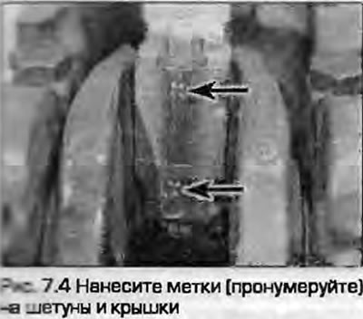
4. Turn the crankshaft until the head and piston No.1 are set to BDC; piston #4 will be installed later. If the pistons and connecting rods are not numbered, mark them (on pistons, caps and connecting rods) using a punch (Fig. 7.4). Remember the orientation of the caps in relation to the connecting rods - at this stage the manufacturer's marks can be difficult to see - draw arrows to ensure correct installation during assembly.
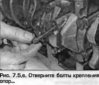
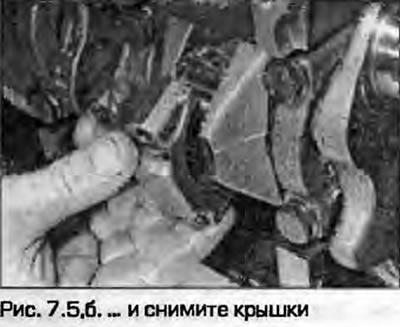
5. Unscrew the bolts/nuts securing the covers. Remove the cover together with the insert (fig. 7.5, a, b). If you are going to reinstall the liners, tape them to their lids.
 |
 |
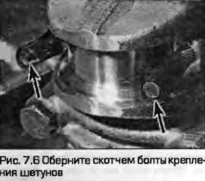
6. If the covers are secured with nuts, wrap the threaded portion of the bolts with tape to avoid scratching the shaft journals during removal and installation (Fig. 7.6).
7. Push the connecting rods upwards, using the wooden handle of a hammer, and remove them from the engine together with the pistons
attention should be paid to the fact that the upper unworn belt of the cylinder may damage the piston or the rings when removing it. However, it is reasonable to note that with such wear, both the pistons and the rings will need to be replaced. If the piston and connecting rod are intact, tie the removed upper liner to them. On engines with piston oil cooling nozzles, be careful not to damage them when removing the pistons.
8. Remove piston #4 in the same manner and rotate the crankshaft half a turn. Remove pistons #2 and #3. Keep the removed components in groups until assembly to be installed in their proper places.
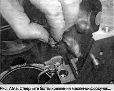
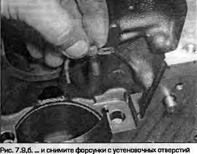
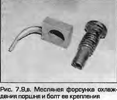
9. If necessary, loosen the mounting screws and remove the oil jets at the bottom of the cylinders (fig. 7.9, a-c).
 |
 |
Examination
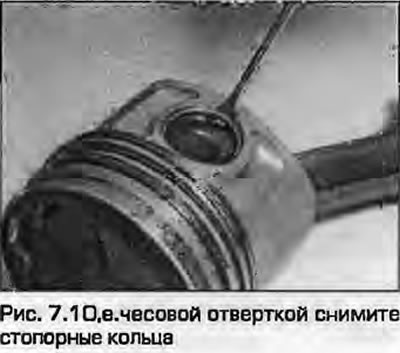
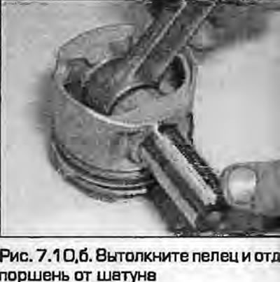
10. Using a watchmaker's screwdriver, remove the pin retaining rings from all pistons. Push the pins out and separate the pistons from the connecting rods (fig. 7.10, a, b). Vibrate the retaining rings - new ones are required for installation. If the pin does not come out - heat the piston to 60°C in hot water - this will make removal easier.
 |
 |
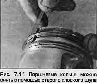
11. Before checking the pistons, remove the piston rings using a puller or flat feeler gauges. Always remove the top compression ring first, stretching it over the piston crown. The rings are very fragile and can break if stretched too much - protect your hands from cuts on the sharp edges of the rings and your eyes from decomposing fragments. After removing the rings, throw them away - install new rings when repairing the engine (Fig. 7.11).
12. Remove carbon deposits from the piston grooves using old rings or their fragments (avoid cutting yourself on the sharp edges of the rings). Remove only carbon deposits, do not remove metal or scratch grooves. Protect your hands - wear gloves.
13. Scrape off any traces of carbon from the piston crown. A hand wire brush or a piece of sandpaper will help remove the bulk of the carbon.
Note: When cleaning pistons, keep their numbers and installation marks.
14. After finishing cleaning the pistons, wash the connecting rods with kerosene or another suitable solvent, dry them thoroughly. Make sure that the oil passage holes in the piston grooves are not clogged with carbon.
15. If the cylinder surface is not significantly damaged and the block does not require boring, the old pistons can be installed. Normal piston wear is manifested as vertical bald spots on the piston rubbing surfaces and a slight glorification in the fit of the upper compression ring. New pistons should always be installed during major repairs.
16. Carefully inspect the pistons - there should be no cracks in the piston bosses, skirt and partitions. Check the pistons for scoring on the rubbing surfaces, burnouts on the bottom and partitions. If the piston has scoring or cavities, the engine may have overheated or the fuel combustion was incorrect, which caused particularly high temperatures in the combustion chamber. In such cases, it is necessary to check the cooling and lubrication systems. Burnouts on the piston skirt indicate that the rings did not seal the piston/cylinder gap. Burnouts on the piston bottom indicate possible incorrect ignition timing, injection timing, detonation. If the above problems are present, the cause must be eliminated, otherwise the engine will fail again. In gasoline engines, these reasons may be caused by a lean mixture due to air suction at the intake. In diesel engines, faulty injectors may be to blame.
17. Check the lugs, connecting rods, pins and connecting rod caps for cracks. Place the connecting rods on a flat surface and, looking along the connecting rod, check for any bending. If there is any doubt about the working condition of the connecting rod, ask specialists from a suitably equipped workshop to weld it. Check for signs of wear and damage to the connecting rod upper head bushing.
18. Using a micrometer, measure the piston diameters at a point 10 mm above the skirt at a right angle to the pin axis (Fig. 6.18). Compare the measurements obtained with the data given in Specifications. If the piston dimensions are outside the acceptable range, the pistons require replacement.
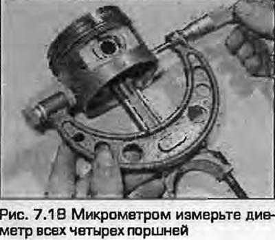
Note: If the cylinder block was previously rebored to oversize, oversize pistons must be installed. Record the measurements and use them to check piston/cylinder clearances when measuring cylinder bores as described below.
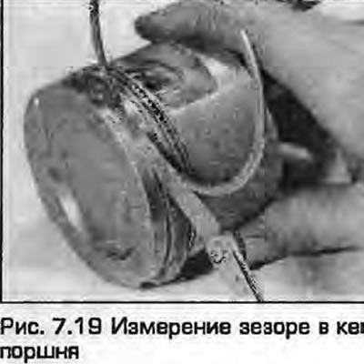
19. Install a new piston ring in the appropriate groove and measure the gap between the partition and the ring using a flat feeler gauge (Fig. 7.19). Note that the rings are of different thicknesses - install the rings in the grooves. Compare the measurements obtained with the data given in Specifications. If the clearances are outside the permissible limits, the pistons must be replaced. Confirm the result by measuring the ring thickness.
20. If there is wear or damage to the pin, the pin and the bushing of the upper connecting rod head can be replaced. It is better to entrust this work to specialists of the auto repair shop.
21. When connecting the piston to the connecting rod, they must be oriented accordingly. There is an arrow on the piston bottom (it may be contaminated with carbon deposits) (fig. 7.21,a,b). When installing the piston in the block, the arrow should point forward of the engine. The connecting rod together with the cover have milled projections ("8" in Fig. 7.21). Both projections should face the engine (Fig. 7.21). The piston with the connecting rod must be assembled in compliance with these requirements.
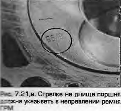
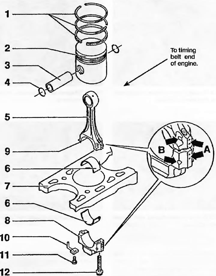
Fig. 7.21, b. Piston components (engine 1Z is shown, the rest are similar): 1. Piston rings; 2. Piston; 3. Finger; 4. Retaining ring; 6. Connecting rod bearing; 7. Upper surface of the cylinder block; 8. Connecting rod bearing cap; 9. Guide bushing (if any); 10. Piston cooling oil nozzle; 11. Oil nozzle mounting screw; 12. Connecting rod bearing cap fastening bolts; A. Identification marks on the connecting rod and cover; B. Connecting rod and cap orientation marks
22. Lubricate the pin and the upper head bushing with pure engine oil, insert the pin into the piston, aligning it with the upper head. Install new retaining rings on both sides of the pin. Repeat the procedure with the remaining pistons.
The original material is located on the website: audimanual.ru