
Table of contents: Removal ↓ Installation ↓
Removal
1. Place the vehicle on a firm, level surface with sufficient space around it.
2. Remove the battery - see chapter 5A.
3. Place chocks under the rear wheels, apply the handbrake. Loosen the front wheel mounting bolts. Raise the front of the car and install safety supports.
4. If installed, unscrew the mounting screws and remove the powertrain protective cover from under the vehicle.
5. If provided, remove the top engine cover (Fig. 4.5).

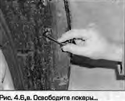
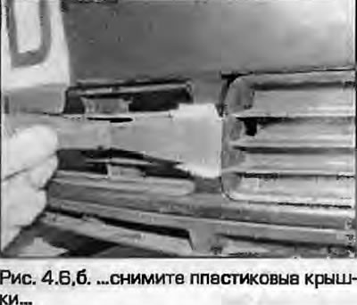
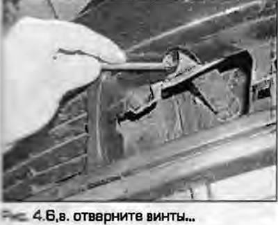
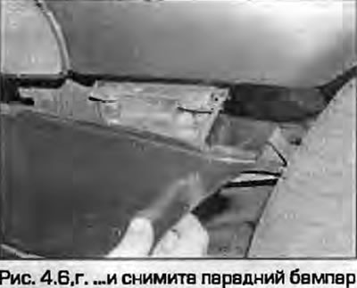
6. Remove the front bumper as described in chapter 11 (Fig. 4.6).
 |
 |
 |
 |
7. As described in chapter 1A, do the following:
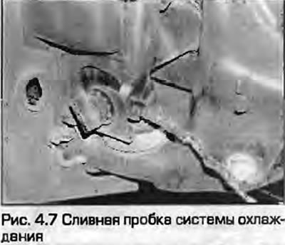
- a) Drain the coolant. The drain plug is located at the front left of the radiator (Fig. 4.7), on some engines there is another plug located in the water pump bearing housing.
- b) Drain the engine oil.
8. Unscrew the two bolts securing the power steering cooling pipe to the front of the radiator and move it to the side. Tie the outside temperature sensor in place.
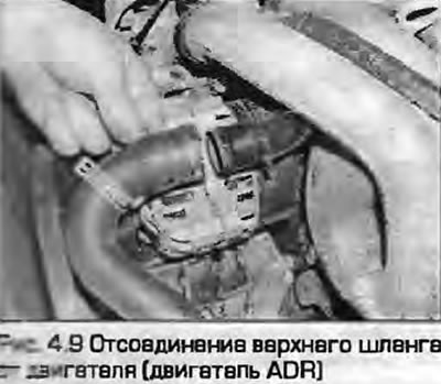
9. Loosen the clamps and disconnect the upper and lower radiator hoses. On an ADR engine, the upper hose is easier to disconnect from the engine (Fig. 4.9). On AHL engines, disconnect the hoses from the engine oil cooler and drain any remaining coolant.
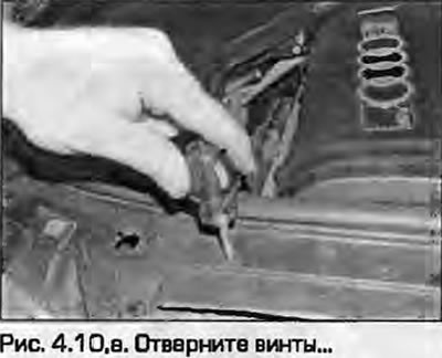
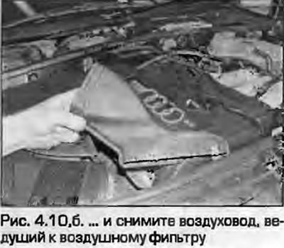
10. Remove the air duct leading from the hood lock bracket to the air filter (fig. 4.10, a, b).
 |
 |
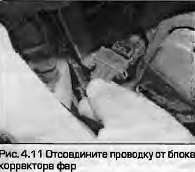
11. Disconnect the wiring from the headlights and headlight beam corrector units (Fig. 4.11).
12. Disconnect the bulb holders from the front direction indicators (Fig. 4.12).

13. Disconnect the hood lock control cable from the lock bracket.
14. On models with an electric cooling fan, disconnect the wiring from the thermostatic sensor located at the bottom left of the radiator. Move the wiring to the side.
15. Disconnect the wiring from the horns and move it to the side.
16. On models equipped with air conditioning, unbolt and remove the air deflectors on both sides of the radiator, then unbolt the condenser. Disconnect the wiring from the low pressure sensor and disconnect the wiring from the electromagnetic clutch of the air conditioner at the bottom of the hood lock bracket. Remove the condenser from the bracket, unfold it and tie it to the front wheel to secure it when removing the engine - cover the condenser with cardboard or rags.
Caution! Do not open the refrigerant circuit of the air conditioner under any circumstances.
17. On models with automatic transmission, place a suitable container under the radiator, loosen the union nuts and disconnect the hydraulic pipes from the bottom of the radiator. Plug the pipes and holes in the radiator to prevent dirt from getting in. Also remove the pipe mounting bracket from the engine.
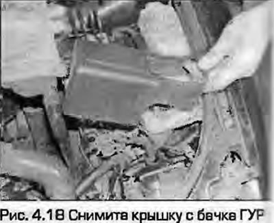
18. Remove the cover from the power steering reservoir (Fig. 4.18).
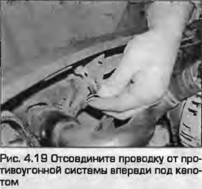
19. Disconnect the wiring from the ABS units, which are located in the left part of the engine compartment and from the anti-theft system sensor under the hood in front (Fig. 4.19).
20. At the top left of the hood lock bracket, disconnect the anti-theft system wiring connector.
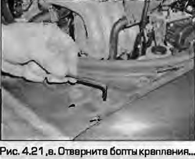
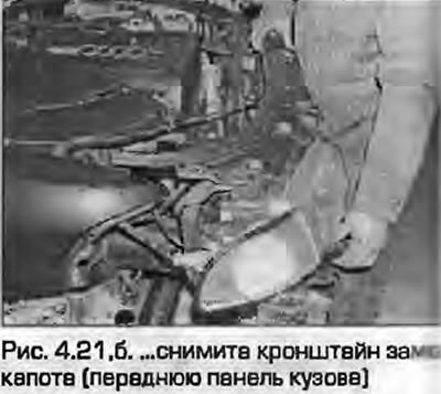
21. Loosen the hood lock bracket mounting bolts, then, with the help of an assistant, remove the entire front panel and move it as far away from the body as possible (fig. 4.21, a, b).
 |
 |
22. Remove the air filter assembly together with the air ducts.
23. Disconnect the central wire of the ignition system, disconnect the wiring, move it away from the engine. If necessary, disconnect the wiring from the oxygen sensor.
24. As described in chapter 4A, relieve the pressure in the fuel system and disconnect the supply and return lines of the fuel rail.
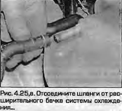
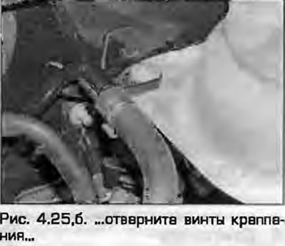
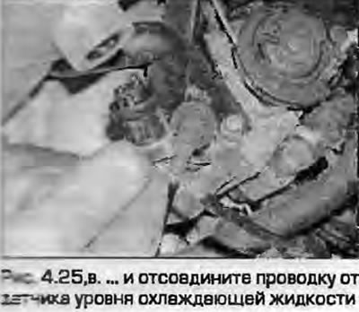
25. Loosen the clamps and disconnect the small hoses from the coolant expansion tank on the left side of the engine compartment. Disconnect the wiring from the coolant level drop sensor, remove the expansion tank (fig. 4.25, a-c).
 |
 |
26. On models with cruise control, disconnect the actuator rod from the throttle control and remove the vacuum hose from the vacuum block.
27. Disconnect the accelerator cable from the throttle body and mounting bracket and move it to the side.
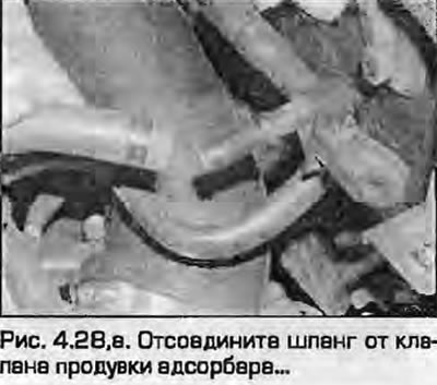
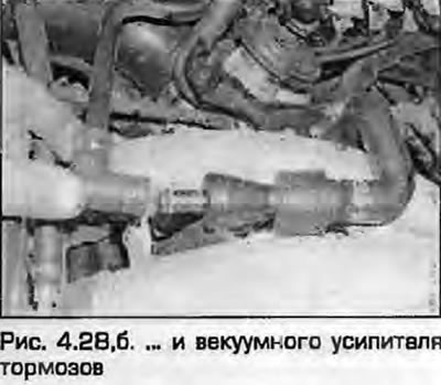
28. Disconnect the vacuum hoses from the charcoal canister purge valve and brake booster (fig. 4.28, a, b).
 |
 |
29. On models with automatic transmission, disconnect the wiring from the kick-down sensor.
30. On left-hand drive models, remove the engine control module from the left side of the firewall as described in chapter 4A. To do this, first remove the cover of the electronic unit, release the clamps and disconnect the wiring. On all models, release the wiring where necessary, unscrew the screw securing the "ground" wire and move the wiring to the side.
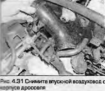
31. Disconnect the crankcase ventilation hoses from the valve cover and throttle body (Fig. 4.31).
32. Loosen the clamps and disconnect the heater hoses from the lower coolant pipe and the outlet flange at the rear of the cylinder head.
33. Disconnect the wiring from the speedometer sensor on the left side of the gearbox.
34. On models with manual transmission, disconnect the wiring from the reverse sensor on the left side of the transmission.
35. Remove the accessory drive belts as described in chapter 2A.
36. As described in Chapter 3, remove the air conditioning compressor from the engine. Tie the compressor to the side.
Attention! Be careful and do not open the refrigerant circuit of the air conditioner under any circumstances.
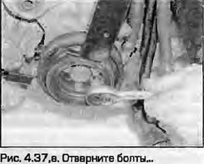
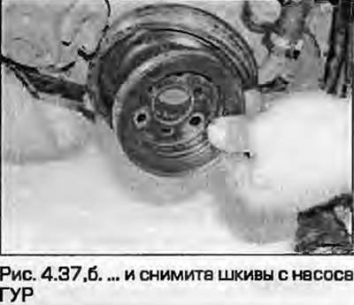
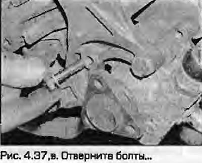
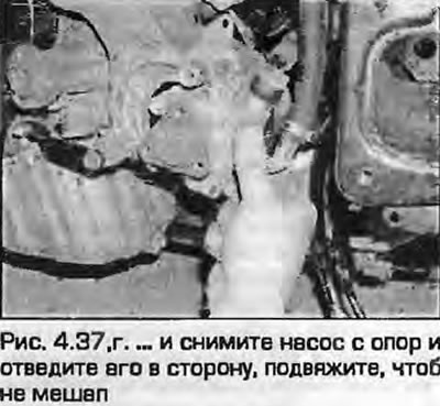
37. Remove the pulley from the power steering pump, remove the power steering pump from the mounting bracket and tie it up, moving it to the side (fig. 4.37, a-g). Do not disconnect the hydraulic hoses and tubes from the pump.
 |
 |
 |
 |
38. Disconnect the exhaust pipe from the exhaust manifold as described in chapter 4B. Do not bend the flexible section of the exhaust pipe excessively.
39. Remove the heat shield from the right engine mount. Unscrew the upper nuts of the right and left engine mounts. Remove the screw and the ground wire from the right mount.
40. Remove the starter as described in chapter 5A.
41. On models with automatic transmission, unscrew the three torque converter mounting nuts, which are now accessible through the starter hole. In order to unscrew all the nuts, the engine will have to be turned. To prevent the faceplate from turning while loosening the nuts, insert a screwdriver between the teeth of the ring gear or hold the crankshaft by the central bolt securing the sprocket.
42. Mark the engine mount positions on the subframe to ensure proper installation later. Loosen the lower mount nuts a few turns.
43. Attach the hoist to the engine and lift the power unit slightly. Make sure that the engine is securely fastened to the hoist.
44. Loosen the bolts securing the gearbox to the rear of the engine, lower the engine into place. Leave one bolt in this position.
45. Place a trolley jack under the gearbox, placing a piece of board between them. You can transfer the weight of the gearbox to a beam placed in the wing grooves.
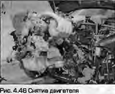
46. Remove the last bolt. Make sure all wires and hoses are disconnected and remove the engine from the engine compartment (Fig. 4.46). On models with automatic transmission, make sure that the torque converter remains inside the bell housing and does not fall. Secure it in the bell housing by screwing an iron strip across the bell housing with two bolts.
47. If the guide bushings are loose, remove them from the rear of the block. If necessary, remove the intermediate plate from the rear of the engine.
48. On models with manual transmission, remove the clutch as described in chapter 6.
Installation
49. Installation - reverse procedure. Before installation on models with manual transmission, lubricate the gearbox shaft splines with a small amount of high-temperature grease. Lightly lubricate the contact surface of the release bearing, but DO NOT lubricate the release bearing guide sleeve. On models with automatic transmission, check the correct installation of the torque converter on the automatic transmission shaft by measuring the distance between the mating surface of the bellhousing and the surface of the torque converter should be approximately 23.0 mm. If only 13 mm, the torque converter is not fully inserted into the bellhousing. Make sure that the engine and gearbox mounts are not overloaded, tighten the threaded connections to the prescribed torques. Install all attachments in accordance with the description of the relevant chapters. Fill the engine with clean engine oil and fill the system with coolant as described in chapter 1A.