Repair Chevrolet Repair Toyota Repair Honda Repair AvtoVAZ Repair Mercedes-Benz Repair BMW Repair Opel
Home  |  Contacts  |  Sitemap  |    
English Русский
Български
Беларускі
Український
Српски
Hrvatski
Română
Polski
Slovenský
Magyar
AudiManual.ru


  • AUDI 80
  • AUDI 100
  • AUDI A3
  • AUDI A4
  • AUDI A6
  • AUDI A8
  • AUDI Q
  • OTHER
  • ARTICLES
B8 (2007-2015) B7 (2004-2008) B6 (2000-2006) B6 (2000-2006, petrol) B5 (1994-2001) B5 (1994-2001, petrol)

Cylinder Block — Cleaning and Checking (Audi A4 B5)

  • Home
  • Audi A4
  • B5 (1994-2001)
  • Power unit
  • Engine overhaul
  • Cylinder Block — Cleaning and Checking
            0
Table of contents: Cleaning ↓ Examination ↓

Cleaning


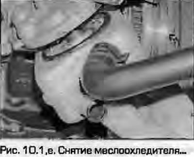
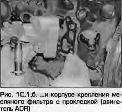
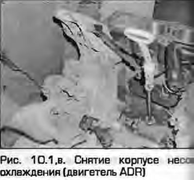
1. Remove all external components and electrical sensors from the block. For a complete cleaning, ideally remove the process plugs from the cylinder block. To remove them, drill a small hole, then screw in a self-tapping screw and remove the plug using pliers or an impact puller (fig. 10.1, a-c).

1. Remove all external components and electrical sensors from the block. For a complete cleaning,…

1. Remove all external components and electrical sensors from the block. For a complete cleaning,…


2. Scrape off all traces of old gaskets, being careful not to damage the mating surfaces.


3. Remove the oil channel plugs. The plugs are usually screwed in very tightly - they can be drilled out, new threads cut and new plugs screwed in during assembly.

4. If the block is very dirty, it can be pressure steam washed. After cleaning the outside surfaces, clean all the passages. Rinse them with hot water until clean water flows out. Dry thoroughly and apply a layer of oil to the treated surfaces to prevent corrosion. Lubricate the cylinders as well. If you have access to an air compressor, use it to speed up the drying and blow out all the passages.

Caution! Be careful and wear safety glasses when working with compressed air.


5. If the parts are not very dirty, they can be washed with hot water (how much can you bear) soapy water with a stiff brush. Regardless of the method used, clean and dry all passages and openings thoroughly. Protect them from corrosion as described above.

6. All threaded holes must be clean so that the bolts can be tightened to the specified torque without fear of cracking the block. To remove rust, residual locking compound and dirt from the threaded holes and to restore the thread profile, run a suitable tap through the holes (Fig. 10.6). If possible, blow out the threaded holes with compressed air. It is useful to use a desiccant spray with a straw, which is usually included with the can (like WD-40).

6. All threaded holes must be clean so that the bolts can be tightened to the specified torque…


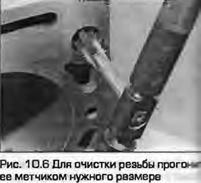
Note: Pay special attention to ensure that no liquids or oils remain in the blind threaded holes - when screwing bolts into them, cracks may appear due to hydraulic pressure.


7. Apply a suitable sealant to the oil passage plugs, screw them into the holes in the block and tighten them securely.

8. If you do not plan to assemble the engine immediately, cover it with plastic wrap and store it so that it does not rust.

Examination


9. Visually inspect the block for cracks and corrosion. Check the threaded holes for damage. If there were internal coolant leaks, the cylinder block must be inspected using special equipment to detect hidden cracks. If such defects are found, repair if possible, otherwise replace the block.

10. Check all cylinder/liner surfaces for wear and scoring. There is usually an unworn ring lip at the top of the cylinder/liner that indicates the piston stroke limit. If the roller is not very worn, it may be possible to bore it to a repair size. Consult a suitably equipped workshop for advice.

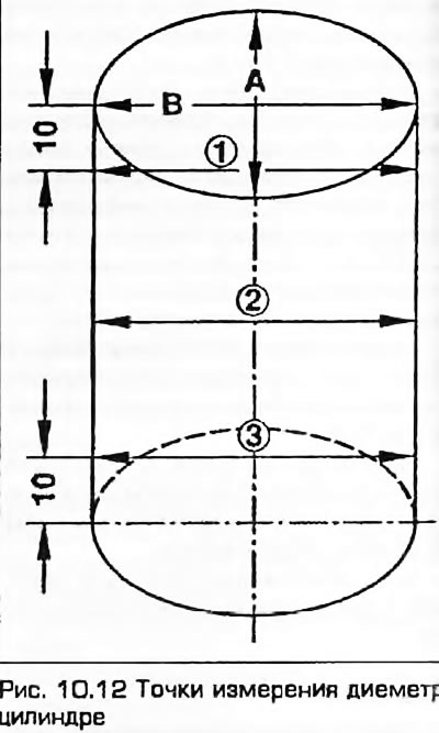
11. Measure the diameter of each cylinder at the top (10 mm below the "fire belt"), in the middle and at the bottom (10 mm from the bottom edge), parallel to the crankshaft axis.

Note: When taking measurements, place the unit on a firm, level surface (workbench). If the engine is mounted on a shaky mounting stand, the measurements may not be accurate.


12. Now take the same measurements, but in a plane perpendicular to the crankshaft axis (fig. 10.12). If the difference between the obtained results exceeds the permissible Specifications, then the cylinder has elliptical or conical wear and radical action must be taken - all four cylinders must be bored to the repair size and the pistons must be replaced with new ones, also of the repair size.


12. Now take the same measurements, but in a plane perpendicular to the crankshaft axis (fig.…


13. Use the piston diameter measurements taken earlier (see paragraph 7) to calculate piston/cylinder clearance. Manufacturers do not specify tolerances, so consult your dealer or engine repair specialist for advice.

14. Place the block on a flat, hard surface with the crankcase facing down. Using a steel ruler and a set of flat feeler gauges, measure the warpage of the mating surface of the block to the head. Tolerances are not defined by manufacturers, but a warpage of 0.05 mm is generally considered acceptable. If the warpage is greater than this value, grinding may be required. Consult your dealer for advice,

15. Before assembling the engine, the cylinder surface should be honed to better fit the rings and achieve maximum sealing. A suitable type of hone has spring-loaded abrasive bars and can be inserted into an electric drill. Experienced car enthusiasts obtain satisfactory results using a plastic bottle covered with sandpaper for this purpose.

Note: If you have access to such a tool, or you are unsure of your ability to handle this task, a specialist can do it for a reasonable fee.


16. To perform this operation you will need one of the above tools, a drill (electric or pneumatic), clean rags, kerosene or honing oil and safety glasses.

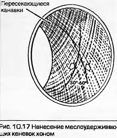
17. Install the hone in the drill chuck. The hone should be given a reciprocating motion to make cross grooves on the cylinder surface, generously pouring honing oil. Ideally, the grooves should intersect at an angle of 50...60° (fig. 10.17). When installing new pistons, their manufacturers may recommend honing at a different angle - follow their instructions.

17. Install the hone in the drill chuck. The hone should be given a reciprocating motion to make…


Caution! Be careful and wear safety glasses when working with compressed air.


18. When honing, generously coat the cylinders with oil. Do not overdo it when removing metal from the cylinders. Do not remove the hone from the cylinder until it stops rotating. Remove the hone by turning it by hand. When finished, wipe off all traces of honing oil with a clean rag.

19. Wipe the cylinder with a rag and move on to the next cylinder. When you are finished honing, wash off any abrasive marks with hot soapy water. The cylinder is clean if after wiping a clean rag soaked in motor oil comes out clean.


20. Coat the block with a thin layer of motor oil to prevent rusting during storage.

21. Install all components removed in accordance with point 1.
The article was checked by auto expert Timur Bazhenov
This article is available at russian, bulgarian, belarusian, ukrainian, serbian, croatian, romanian, polish, slovak, hungarian

Share information:
Previous articles
Audi A4 B5: Engine overhaul
Next articles

Auxiliary shaft — removal and installation
Crankshaft — Removal and Inspection
Pistons and connecting rods — removal and inspection
Cylinder head — disassembly, cleaning, inspection and assembly
Crankshaft bearings — inspection and selection
Engine Repair — Assembly Sequence
Crankshaft — checking clearances in main bearings and…
Pistons and piston rings — assembly


Similar articles on other Audi car models:
Technical characteristics of the cylinder block Audi 80 B2 (1979-1986)
Cylinder block/crankcase — cleaning and inspection Audi 100 C3 (1982-1990, diesel)
Checking the vehicle's readiness for operation Audi A3 Type 8L (1996-2003)
Checking/cleaning water drainage hoses Audi A6 C5 (1997-2004)
Checking the exhaust system Audi A8 D2 (1994-2002)
Belt pulley cylinder block Audi Q5 Type 8R (2008-2017)
Air filter — cleaning the housing and replacing the filter… Audi A2 (1999-2005)
Link to this page in different formats


Visitor comments

No comments yet


How much will 36 + 16 =


A4(B8, 2007-2015) 
  • General information
  • Operating instructions
  • Power unit
  • Petrol engines 1.8 l
  • Petrol engines 1.8/2.0 l
  • Petrol engines 3.0 l
  • Petrol engines 3.2 l
  • Fuel system (petrol)
  • Diesel engines 2.0 l (CA*)
  • Diesel engines 2.0 l (CJCB)
  • Diesel engines 2.7/3.0 l
  • Diesel engines 3.0 l
  • Fuel system (diesel)
  • Transmission
  • Manual gearbox 0B1
  • Manual gearbox 0B2
  • Manual gearbox 0B3
  • Manual gearbox 0B4
  • Automatic transmission 0B5
  • Automatic transmission 0B6
  • Automatic transmission 0AW
  • All-wheel drive system
  • Chassis
  • Front suspension
  • Rear suspension
  • Brake system
  • Steering system
  • Body
  • Exterior
  • Interior
  • Seats
  • Doors, locks and windows
  • Security system
  • Heating and air conditioning
  • Electrical equipment
  • Audio system
  • Power devices
  • Equipment and devices
  • Lighting and lamps
  • Electrical circuits
 
A4(B7, 2004-2008) 
  • General information
  • Introduction to manual
  • Troubleshooting
  • Operating instructions
  • Maintenance
  • Power unit
  • Petrol engines 2.0 (ALT)
  • Petrol engines 2.0 (TFSI)
  • Petrol engines 1.8 (MPI)
  • Diesel engines
  • Cooling system
  • Air conditioner
  • Fuel and exhaust system
  • Ignition system
  • Starting and charging
  • Transmission
  • Clutch
  • Manual gearbox
  • Automatic gearbox
  • Drive shafts
  • Chassis
  • Brake system
  • Front suspension
  • Rear suspension
  • Steering
  • Body
  • Exterior
  • Interior
  • Electrical equipment
  • Equipment and devices
  • Lighting and signaling
  • Windscreen wipers and washers
  • Electrical diagrams
  • Electrical diagrams (since 2007)
 
A4(B6, 2000-2006) 
  • General information
  • Vehicle Description
  • User manual
  • Maintenance
  • Power unit
  • Gasoline engine
  • Diesel engine
  • Lubrication system
  • Cooling system
  • Supply system
  • Injection system
  • Exhaust system
  • Ignition and control
  • Transmission
  • Gear box
  • Clutch and drive shafts
  • Chassis
  • Brake system
  • Car suspension
  • Steering
  • Body
  • Heating and ventilation
  • Exterior (external elements)
  • Interior (internal elements)
  • Electrical equipment
  • Power devices
  • Lighting and appliances
  • Electrical circuits
 
A4(B6, 2000-2006, petrol) 
  • General information
  • Introduction to the guide
  • Car care
  • Power unit
  • Engine repair
  • Lubrication system
  • Cooling system
  • Injection and control system
  • Ignition system
  • Power and exhaust system
  • Transmission
  • Clutch and drive shafts
  • Car gearbox
  • Chassis
  • Suspension and wheels
  • Steering
  • Brake system
  • Body
  • Interior
  • Exterior
  • Electrical equipment
  • Equipment and devices
  • Lighting and signaling
  • Power devices
  • Electrical circuits
 
A4(B5, 1994-2001) 
  • General information
  • Introduction to the guide
  • Car care
  • Maintenance (gasoline)
  • Maintenance (diesel)
  • Power unit
  • Gasoline engines
  • Diesel engines
  • Engine overhaul
  • Cooling system
  • Fuel injection (gasoline)
  • Fuel system (diesel)
  • Exhaust system
  • Ignition system
  • Transmission
  • Clutch
  • Mechanical gearbox
  • Automatic gearbox
  • Drive shafts
  • Chassis
  • Brake system
  • Car suspension
  • Steering
  • Body
  • Exterior
  • Interior
  • Doors, locks and windows
  • Heating and ventilation
  • Electrical equipment
  • Power devices
  • Equipment and devices
  • Electrical circuits
 
A4(B5, 1994-2001, petrol) 
  • General information
  • Vehicle description
  • Maintenance
  • Power unit
  • Engine repair
  • Turbocharging
  • Exhaust system
  • Cooling system
  • Ignition system
  • Fuel system
  • Motronic injection system
  • MPI and MPFI injection system
  • Transmission
  • Clutch
  • Gearbox and shafts
  • Chassis
  • Steering
  • Car suspension
  • Brake system
  • Wheels and tires
  • Body
  • Heating and ventilation
  • Body parts
  • Electrical equipment
  • Fuses and relays
  • Power devices
  • Lighting and lamps
  • Tools and devices
  • Electrical circuits
 
AudiManual.ru © 2017-2026 · Mobile version · Feedback · Sitemap: EN BG BY UA RS HR RO PL SK HU · Site search · News and articles
80 B2 · 80 B3 petrol · 80 B3 · 80 B4 · 100 C3 diesel · 100 C3 petrol · 100 C3 · 100 C4 petrol · 100 C4 · A3 Type 8L · A4 B5 petrol · A4 B5 · A4 B6 petrol · A4 B6 · A4 B7 · A4 B8 · A6 C4 · A6 C5 · A6 C5 Allroad · A8 D2 · Q5 Type 8R · Q7 Typ 4L · Audi A2 ·
This site uses cookies 🍪. Click the button to accept this fact.