
Table of contents: Installation and checking of gaps ↓ Final installation of pistons with… ↓
Installation and checking of gaps
Note: This step assumes that the crankshaft is installed on the engine as described in paragraph 13.
1. As with main bearings, connecting rod bearings also need to provide the necessary clearance for oil circulation. There are two ways to measure clearance, described below.
2. Install the cylinder block on a clean work area, with the crankcase facing up. Install the crankshaft with the connecting rod collar of the first cylinder facing up.
3. The first method is less accurate and involves installing connecting rod bearing caps on connecting rods with bearing shells installed.
Note: Install the covers correctly as described in paragraph 7. The inner diameter of the connecting rod bearing is measured with a bore gauge. If the diameter of the corresponding washer is subtracted from the obtained value, the result can be obtained - the clearance in the connecting rod and bearing.
4. The second method is to use "Plastigauge", in the same way, in case of measuring the clearance in the main bearings (see paragraph 13). This method is much more accurate than the previous one. Wipe the journals with a clean, lint-free cloth. Starting from the journal of the first connecting rod, lay out pieces of plastic rod parallel to the shaft axis.
5. Pull the connecting rod to the shaft journal. Make sure that the marks on the cap and connecting rod match and install the cap.
6. Tighten the cover mounting bolts/nuts as specified Specifications. without rotating the crankshaft.
7. Remove the cover without rotating the crankshaft. Apply the spatula from the kit "Plastigauge" to the crushed section of the plate, calculate the clearance in the bearing. Compare the obtained data with those given in Specifications.
8. If the gaps are outside the permissible limits, the inserts may be of the wrong size (or excessively worn out previous ones). Make sure that no dirt or oil got under the bearings when measuring. Check the journal diameter again. If the flattened plastic rod has different widths at the edges, the journal may be tapered. Eliminate the cause by grinding the journal or replacing the bearings.
9. 8 Finish by carefully scraping away any plastic residue from the surface of the neck or liner using a soft scraper - a metal one may leave delicate scratches.
Final installation of pistons with connecting rods
10. 8 This stage assumes that the crankshaft and bearing caps are installed as described in paragraph 13.
11. Make sure the bearings are installed correctly. If you are installing new bearings, remove the preservative with kerosene. Wipe the bearings and journals dry with a lint-free cloth.
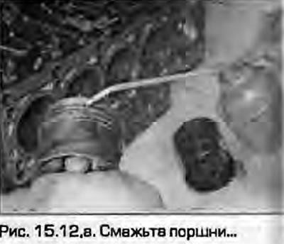
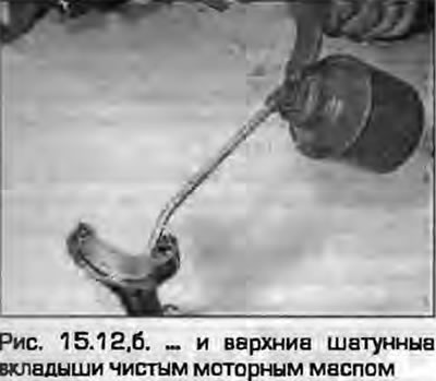
12. Lubricate the cylinder walls, pistons with rings and shaft journals with engine oil (fig. 15.12, a, b). Lay out the pistons in order. If the connecting rod caps are secured with nuts, wrap them with tape to avoid making unnecessary scratches when installing them into the block.
 |
 |
13. Start installation with the first cylinder. Make sure that the ring locks are correctly set as described in paragraph 14, compress them with a ring compressor (universal "crimping tool").
14. Insert the piston into the top of the first cylinder. If oil jets are installed, try not to damage them when installing the pistons.
15. Make sure that the piston is correctly oriented in the block - the piston crown, connecting rod and cap have marks that should face the timing belt, as described in paragraph 7.
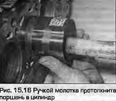
16. Using a wooden hammer handle, lightly tap the bottom of the piston until the piston is flush with the mating surface of the block (fig. 15.16).
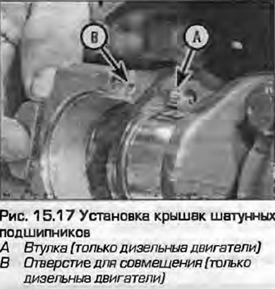
17. Make sure that the bearing has not shifted. Lubricate the bearing and journal with clean engine oil. Trying not to stain the cylinder walls, push the piston down so that the bearing aligns with the crankshaft journal. Remove the tape from the bolts, if you wrapped them. Lubricate the threaded part of the bolts and the underside of the bolt head. Install the cover and tighten the bolts/nuts of its fastening "by hand" (fig. 15.17). Make sure the cover is oriented correctly - the bearing locks should be on one side, the camshafts on the cover and the connecting rod should be facing the timing belt. If necessary, check the illustrations on the paragraph 7.
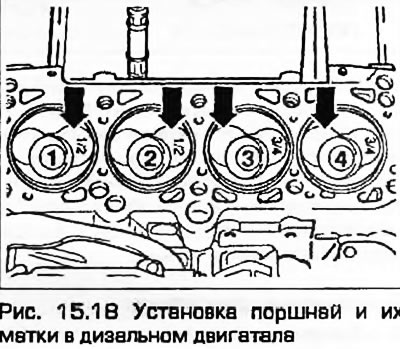
18. On diesel engines the piston crowns are machined differently to ensure correct combustion process pistons 1 and 2 are different from pistons 3 and 4. If the pistons are installed correctly the largest recess for the larger inlet valve of cylinders 1 and 2 should face the flywheel/faceplate, the largest recess for the larger inlet valve of cylinders 3 and 4 should face the timing belt. New pistons are numbered:? means piston 1 or 2,? means piston 3 or 4 (fig. 15.18).
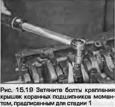
19. Tighten the mounting bolts/nuts to the specified torque for stage 1 (fig. 15.19).
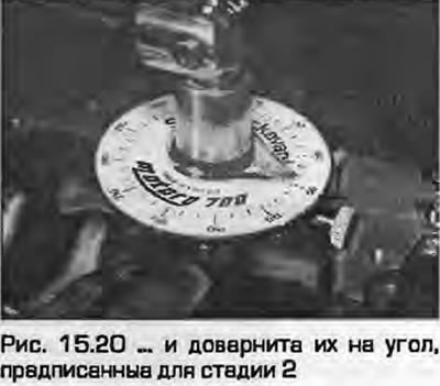
20. Tighten the cover mounting bolts/nuts to the angles specified in stage 2 (fig. 15.20).
21. Install the remaining three pistons with connecting rods in the same manner.
22. Turn the crankshaft by hand. The shaft should rotate freely, without jamming. A small amount of friction is allowed if new parts are installed, but it should be uniform.
Diesel engines
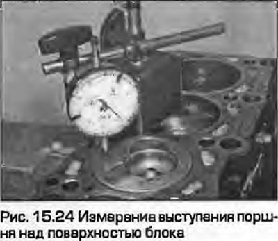
23. If you are installing new pistons, or a new block assembly with pistons and crankshaft, you must measure the piston protrusion above the block surface to calculate the required gasket thickness.
24. Turn the block over, installing it with the crankcase down, and place it on wooden blocks. Attach a dial indicator to the block. Place the measuring device leg on the mating surface and zero the readings. Move the leg to the bottom of piston No.1 and smoothly turn the crankshaft until the piston is at TDC. Measure the piston protrusion above the block surface in this position (fig. 15.24).
25. Repeat the procedure with the remaining pistons, recording the results
26. If the results vary from piston to piston, take the highest value as a basis and calculate from it the required gasket thickness, using the data given in specifications.
27. If you are installing the same pistons, install a new gasket of the same thickness as the old one.
All engines
28. Finally, install the oil pump and oil pan, baffle plate and pan, flywheel and cylinder head as described in Chapter 2A or 2B.
(Material republished from the website: audimanual)