
Table of contents: Checking the working clearance of… ↓ Piston/Connecting Rod Assemblies -… ↓
Checking the working clearance of the connecting rod bearing
Note: At this stage the crankshaft should be installed in the engine (see Chapter 12).
1. As with the main bearings, there must be a working clearance between the crankshaft journal and the bearing shells. There are two methods for checking the clearance.
2. Place the cylinder block on a clean, level work surface with the crankcase facing up. Turn the crankshaft so that the connecting rod journal of cylinder #1 is at BDC.
3. The first method is less accurate and consists of installing bearing caps on the connecting rods outside the crankshaft (liners in working position) Measure the inside diameter of the assembled big end of the connecting rod using a bore gauge. Then subtract the diameter of the corresponding crankshaft journal from this, which will give you the bearing operating clearance.
Note: Correct orientation of the bearing caps is critical (see Note in Chapter 7).
4. The second method involves using the Piastigage tool in the same way as when checking the main bearing clearance (see Chapter 12) and it is much more accurate than the previous method. Wipe all the crankshaft journals with a clean cloth. Place a piece of Piastigage thread on the bearing journal.
5. Install the upper bearing shell into the connecting rod, making sure its locating lug fits into the corresponding groove. Install the piston/connecting rod assembly onto the crankshaft, then install the bearing cap using the manufacturer's marks.
6. Tighten the bearing cap nuts/bolts to Stage 1 torque, being careful not to dislodge the Plastigage thread or turn the connecting rod.
7. Disassemble the assembly without moving the connecting rod. Use the scale printed on the Plastigage package to determine the connecting rod bearing running clearance and compare the result with the data given in Specifications.
8. If the gap does not correspond to the specified values, it is possible that the inserts installed are of the wrong size (or they are excessively worn if the old liners are installed). Make sure there is no dirt or oil trapped between the bearings and the cap or connecting rod. Re-measure the crankshaft journal diameter. Note that if one end of the Plastigage is wider than the other, the crankshaft journal may be tapered and require regrinding.
9. When finished, carefully scrape all traces of Plastigage from the crankshaft and bearing shells. Use a plastic or wooden scraper that will not scratch the working surfaces.
Piston/Connecting Rod Assemblies - Final Installation
10. Please note that the following procedure assumes that the crankshaft main bearing caps are already in the operating position (see Chapter 12).
11. Make sure the bearing shells are installed correctly (see the beginning of this Chapter). If new bearings are being installed, wash off all traces of protective grease with kerosene. Wipe the bearings and connecting rods dry with a thick (lint-free) cloth.
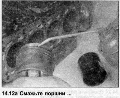
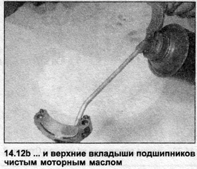
12. Lubricate the cylinder walls, pistons, piston rings and upper bearing shells with clean engine oil (see illustrations). Lay out the piston/rod assemblies in the correct order on the workbench. Where the bearing caps are secured with nuts, tape the threaded ends of the studs with electrical tape to avoid scratching the crankpins and cylinders when installing the pistons.
13. Begin by assembling piston/connecting rod #1. Make sure the piston ring joints are still positioned as described in Chapter 13, then press them into the grooves using a special compressor.
14. Insert the piston/connecting rod assembly into the top of cylinder #1. Guide the small end of the connecting rod so that it does not damage the cylinder walls. Where the oil jets are installed, be very careful not to break them when installing the connecting rods onto the crankshaft journals.
15. Make sure the piston is correctly oriented in the cylinder - the piston head, connecting rods and connecting rod bearing caps have marks that should be facing towards the front end of the engine (see Chapter 7).
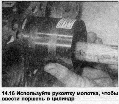
16. With the hammer handle resting on the piston head, insert the assembly completely into the cylinder so that the piston head is flush with the top edge of the cylinder (see illustration).
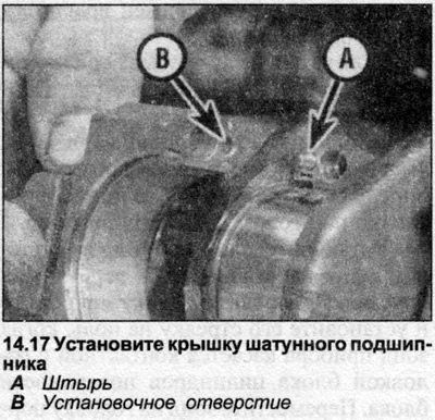
17. Check that the bearing shell has not shifted. Liberally lubricate the crankshaft journal and both bearing shells with clean engine oil. Taking care not to scratch the cylinder walls, drive the piston/connecting rod assembly onto the crankshaft journal. Remove from the connecting rod studs (where are there) tape, lubricate the threads and the backs of the bolt heads with oil. Install the connecting rod bearing cap, tightening the mounting nuts/bolts by hand at this stage (see illustration). Please note that the orientation of the bearing cap relative to the connecting rod is critical. The slots of both components, located close to their contact surfaces, should face the front end of the engine (that is, in the direction of the arrow on the piston head) — see illustrations in Chapter 7.
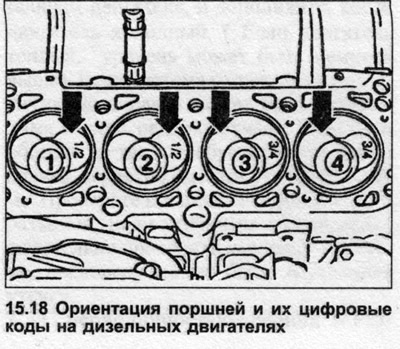
18. On diesel engines, the piston heads have a special shape designed to improve combustion characteristics. Pistons #1 and #2 are different from the other pistons. On them, the large recesses for the inlet valves should face the flywheel, and the large recesses for the inlet valves on the other pistons should face the front end of the engine. New pistons have the numbers on the heads 1/2 (pistons #1 and #2), 3/4 (piston #3 or #4), and 3/4/5 (pistons #3, #4, and #5) (see illustration).
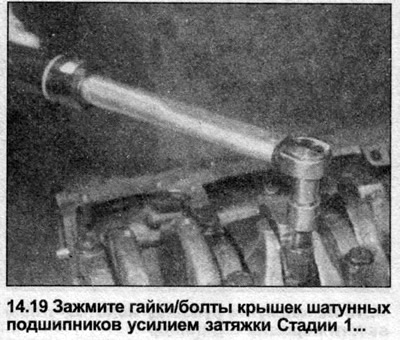
19. Tighten the mounting bolts/nuts to Stage 1 tightening torque (see illustration).
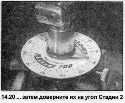
20. Tighten the bolts/nuts to the angle specified in Stage 2 (see illustration).
21. Install the remaining piston/connecting rod assemblies in the same manner.
22. Rotate the crankshaft by hand. Make sure it rotates freely. Some stiffness is normal if new components have been installed, but the shaft should rotate smoothly without binding.
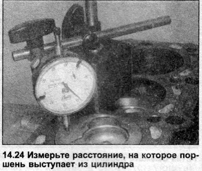
23. If new pistons or a new "short engine" (see Note in Chapter 5), measure the amount by which the piston heads at TDC protrude from the cylinder block to determine the required thickness of the cylinder head gasket.
24. Place the cylinder block with the crankcase down on a stand or wooden blocks. Attach a micrometer to the block and set its pointer to zero when the probe of the device touches the contact surface of the block with the cylinder head. Move the probe to the head of piston No.1 and slowly turn the crankshaft so as to bring this piston to TDC. Record the readings of the device (see illustration).
25. Repeat the measurement on the remaining pistons.
26. If the measurement results are different for different pistons, take the highest value to determine the type of cylinder head gasket - see Specifications.
27. Please note that if the same pistons were installed, the new cylinder head gasket must be identical to the old one.
28. See. Section 1A, and install the oil pump and its intake pipe, the sump and its partition, the flywheel and the cylinder head.
[The article was copied from the website: AudiManual.ru]