Repair Chevrolet Repair Toyota Repair Honda Repair AvtoVAZ Repair Mercedes-Benz Repair BMW Repair Opel
Home  |  Contacts  |  Sitemap  |    
English Русский
Български
Беларускі
Український
Српски
Hrvatski
Română
Polski
Slovenský
Magyar
AudiManual.ru


  • AUDI 80
  • AUDI 100
  • AUDI A3
  • AUDI A4
  • AUDI A6
  • AUDI A8
  • AUDI Q
  • OTHER
  • ARTICLES
C4 (1990-1994) C4 (1990-1994, petrol) C3 (1982-1990) C3 (1982-1990, petrol) C3 (1982-1990, diesel)

Pistons and piston rings — assembly (Audi 100 C3)

  • Home
  • Audi 100
  • C3 (1982-1990, diesel)
  • Power unit
  • Engine removed
  • Pistons and piston rings — assembly
            0
1. At this point the pistons should already be connected to their corresponding connecting rods. If not already done, check the clearances between the rings and the piston groove walls (see Chapter 7).

2. Before installing the rings on the pistons, check their ring gaps as follows.

3. Lay out the piston/connecting rod assemblies and new ring sets on a clean work surface so that related components are together. Place the cylinder block on the workbench so that you can access the top and bottom of the cylinders.

4. Insert the top ring into the first cylinder and align it by lightly pressing it with the piston head. The ring should sit at the base of the cylinder, near the lower limit of the piston stroke.

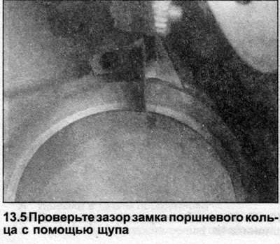
5. By pushing the feeler gauges into the space between the ends of the ring, select a suitable one, the thickness of which is equal to the gap (see illustration). The probe should enter the gap with a small resistance. Compare the measurement result with the data given in Specifications. If the gap size is outside the permissible tolerances, make sure once again that this ring should be in this particular cylinder.

5. By pushing the feeler gauges into the space between the ends of the ring, select a suitable one,…


6. If the gap is too small, it must be increased, otherwise the ends of the ring will rest against each other during engine operation, which will lead to engine damage. Carefully file the ends of the ring with a fine file, clamping the file in a vice with jaws equipped with soft pads. File only the end surface of the ends of the ring. Repeat the procedure on the remaining rings. Do not mix rings from different pistons and do not confuse pistons; keep them near the corresponding cylinder at all times.


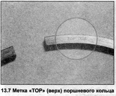
7. Once the ring lock clearances have been checked (and corrected if necessary), the rings can be installed on the pistons. Start installation from the lowest groove (oil scraper ring). Please note that the ring consists of two working parts separated by a spacer part (middle part of oil scraper ring). Note also that the two compression rings have different profiles and must be installed in their respective grooves using a special tool. Both compression rings have marks indicating their top side (see illustration).

7. Once the ring lock clearances have been checked (and corrected if necessary), the rings can be…


8. Position the ring locks so that they are 120° apart.

Note: Please follow the instructions printed on the ring set packaging carefully.


This article was previously published on the resource: AUDIMANUAL.RU
The article was checked by auto expert Nikita Rudakov
This article is available at russian, bulgarian, belarusian, ukrainian, serbian, croatian, romanian, polish, slovak, hungarian

Share information:
Previous articles
Audi 100 C3: Engine removed
Next articles

Crankshaft — installation and checking of working clearance
Engine assembly sequence
Main and connecting rod bearings — inspection and selection of…
Cylinder block/crankcase — cleaning and inspection
Piston/Connecting Rod Assemblies — Installing and Checking…
Engine — Starting after Overhaul


Similar articles on other Audi car models:
Pistons and connecting rods — assembly and installation Audi 80 B3 (1986-1991, petrol)
Setting the piston of the first cylinder to TDC (petrol) Audi A3 Type 8L (1996-2003)
Pistons and piston rings — assembly Audi A4 B5 (1994-2001)
Installing piston rings Audi A6 C4 (1994-1997)
Pistons and connecting rods Audi A8 D2 (1994-2002)
Pistons and connecting rods Audi Q5 Type 8R (2008-2017)
Removal and installation the sealing rings of the pump-injector Audi A2 (1999-2005)
Link to this page in different formats


Visitor comments

No comments yet


How much will 41 + 17 =


100(C4, 1990-1994) 
  • General information
  • User manual
  • Power unit
  • Engine repair
  • Ignition system
  • Fuel system (gasoline)
  • Fuel system (diesel)
  • Lubrication system
  • Cooling system
  • Exhaust system
  • Transmission
  • Clutch
  • Car gearbox
  • Drive shafts
  • Chassis
  • Car suspension
  • Steering
  • Wheels and tires
  • Brake system
  • Body
  • Ventilation and heating
  • Body repair
  • Electrical equipment
  • Power devices
  • Lighting and appliances
  • Electrical circuits
 
100(C4, 1990-1994, petrol) 
  • General information
  • Operation and maintenance
  • Power unit
  • Engine repair
  • Exhaust system
  • Cooling system
  • Supply system
  • Air filter
  • Mono-Motronic injection system
  • Digifant injection system
  • KE-III-Jetronic and KE-Motronic
  • MPI and MPFI injection system
  • Transmission
  • Clutch
  • Car gearbox
  • Chassis
  • Suspension and steering
  • Brake system
  • Wheels and tires
  • Body
  • Exterior
  • Interior
  • Electrical equipment
  • Fuses and relays
  • Power devices
  • Ignition system
  • Lighting and signaling
  • Equipment and devices
  • Electrical circuits
 
100(C3, 1982-1990) 
  • General information
  • User manual
  • Maintenance
  • Specifications
  • Power unit
  • Engines 4-cylinder
  • Engines 5-cylinder
  • Diesel engine
  • Cooling system
  • Power system (carburetor)
  • Power system (injector)
  • Fuel system (diesel)
  • Transistor ignition system
  • Electronic ignition system
  • Transmission
  • Clutch
  • 4 speed gearbox 014
  • 5 speed gearbox 013 and 093
  • 5 speed gearbox 016 and 012
  • Shift mechanism KP 016
  • Automatic transmission
  • Front wheel drive
  • Chassis
  • Front suspension
  • Rear suspension
  • Steering
  • Brake system
  • Body
  • Body elements
  • Electrical equipment
  • Lighting and appliances
  • Power devices
  • Electrical circuits
 
100(C3, 1982-1990, petrol) 
  • General information
  • Maintenance and operation
  • 4 cylinder engine
  • Engine repair
  • Cooling and lubrication system
  • Supply system
  • Ignition system
  • 5 cylinder engine
  • Engine repair
  • Cooling and lubrication system
  • Supply system
  • Ignition system
  • Transmission
  • Clutch and drive shafts
  • 4 speed gearbox 014
  • 5 speed gearbox 013 and 093
  • 5 speed gearbox 016 and 012
  • Automatic gearbox
  • Chassis
  • Steering
  • Front suspension
  • Rear suspension
  • Brake system
  • Body
  • Body elements
  • Doors, locks and windows
  • Body repair
  • Electrical equipment
  • Equipment and devices
  • Power devices
  • Electrical circuits
 
100(C3, 1982-1990, diesel) 
  • General information
  • User manual
  • Maintenance
  • Troubleshooting
  • Power unit
  • Engine in a car
  • Engine removed
  • Cooling system
  • Fuel system
  • Exhaust system
  • Starting and charging
  • Preheating
  • Transmission
  • Clutch
  • Mechanical gearbox
  • Automatic gearbox
  • Drive shafts
  • Chassis
  • Brake system
  • Suspension
  • Steering
  • Body
  • Exterior
  • Interior
  • Electrical equipment
  • Equipment and devices
  • Electrical circuits
 
AudiManual.ru © 2017-2026 · Mobile version · Feedback · Sitemap: EN BG BY UA RS HR RO PL SK HU · Site search · News and articles
80 B2 · 80 B3 petrol · 80 B3 · 80 B4 · 100 C3 diesel · 100 C3 petrol · 100 C3 · 100 C4 petrol · 100 C4 · A3 Type 8L · A4 B5 petrol · A4 B5 · A4 B6 petrol · A4 B6 · A4 B7 · A4 B8 · A6 C4 · A6 C5 · A6 C5 Allroad · A8 D2 · Q5 Type 8R · Q7 Typ 4L · Audi A2 ·
This site uses cookies 🍪. Click the button to accept this fact.