
Removal
1. Remove the timing belt and crankshaft sprocket as described in Chapter 6.
2. Remove the tray as described in Chapter 15.
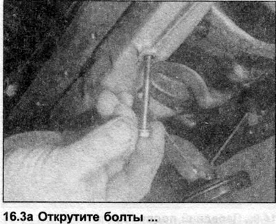
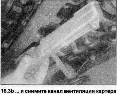
3. Unscrew the bolts and remove the crankcase ventilation duct from the block base (see illustrations).
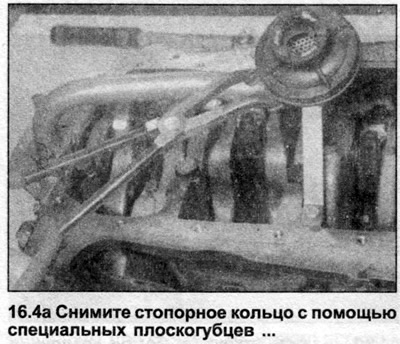
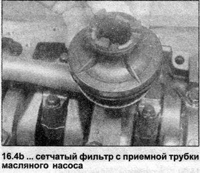
4. Using special pliers, remove the retaining ring of the mesh oil receiver at the base of the oil pump intake tube (see illustrations).
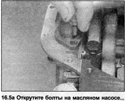
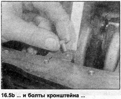
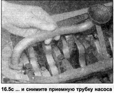
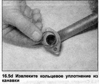
5. Using a screwdriver or similar tool, bend back the tabs on the locking plate. Remove the bolts securing the oil pump inlet pipe bracket to the crankcase, then remove the bolts on the oil pump base and remove the locking plate. Remove the pipe and remove the gasket or O-ring (see illustrations).
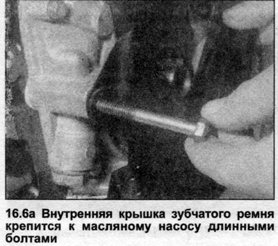
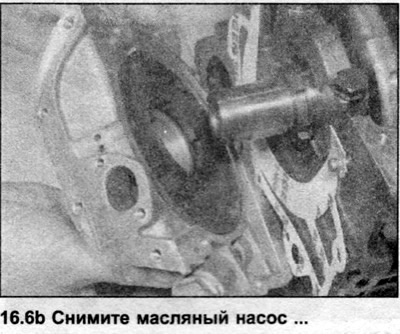
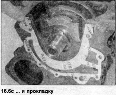
6. Remove the mounting bolts and lift the oil pump out of the front of the cylinder block. Remove the gasket. Note that some of the oil pump mounting bolts also secure the inner timing belt cover (see illustrations).
Inspection
7. Remove the cone head screws securing the pump cover and remove the cover.
8. Make sure that there is a mark on the exposed surface of the pump rotors. If not, make a mark to ensure proper orientation of the rotors during installation.
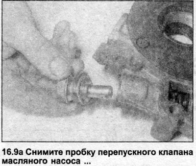
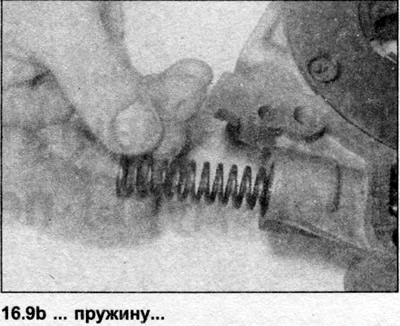
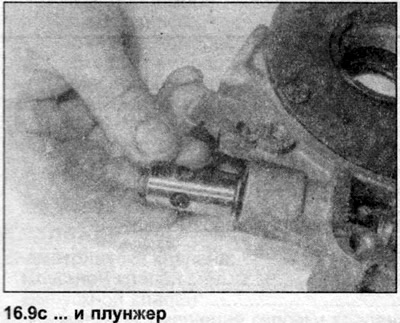
9. Remove the bypass valve plug, O-ring, spring and plunger (see illustrations).
10. Clean all components thoroughly and inspect the pump body and cover for scratches and wear. Inspect the relief valve plunger and guide walls for damage and wear, and make sure the spring is not damaged or deformed. Inspect the rotors for damage and wear. New rotors are not available, so if they are excessively worn, the oil pump must be replaced.
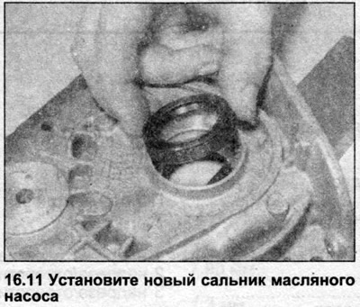
11. Using a screwdriver, carefully pry the seal away from the front wall of the pump. If this is not possible, use a drift, inserting it from the inside of the pump. Lubricate the sealing edge of the new seal with oil, insert the seal with the closed surface facing outward and use a wooden block to press it into the pump so that the seal is flush with the edge of the hole. If there are scratches on the contact surface of the crankshaft with the seal, move the seal a little deeper so that its sealing edge is adjacent to the undamaged part of the crankshaft (see illustration).
12. Reassemble the pump by installing the rotors and cover. The inner rotor should be with the splined side facing the crankshaft, and although the outer rotor can theoretically be installed either way, it should also be oriented as it was when removed. Some rotors have a triangle on them, and this mark should be facing the pump cover. Before installing the cover, fill the gaps between the rotors with oil to ensure immediate oil flow to the engine after it starts.
13. Tighten the cover screws securely.
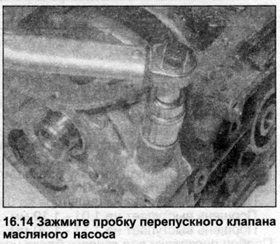
14. Assemble the bypass valve and tighten the plug securely (see illustration).
Installation
15. Install a new gasket onto the cylinder block front wall pins and secure it in place with a small amount of grease.
16. Install the oil pump onto the engine block, making sure the groove on the inner rotor fits into the clamp on the crankshaft. Be careful not to damage the seal on the end of the crankshaft.
17. Insert the bolts and tighten them in a diagonal sequence to the tightening torque specified in the Specifications.
18. Install the oil pickup tube with a new gasket or O-ring and tighten the bolts. Bend the locking tabs onto the bolts to lock them.
19. Install the mesh oil receiver and secure it with the retaining ring.
20. On 1T engines, install the crankcase ventilation channel and tighten the bolts to the tightening torque specified in the Specifications.
21. Install the pan, toothed drive belt and sprocket (see Chapters 15 and 6).
The text is based on materials from the website: AUDIMANUAL.ru