
Table of contents: Intake manifold ↓ Removal and installation the high… ↓ Adaptation of injectors ↓ Removal and installation injectors ↓
Intake manifold
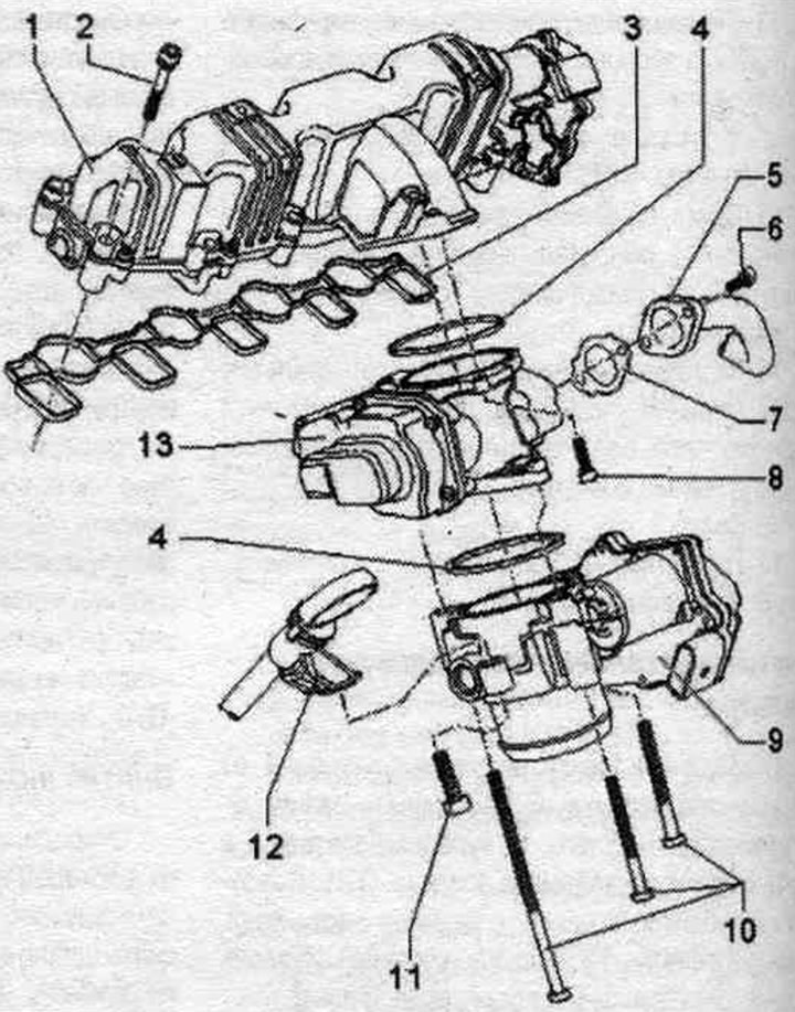
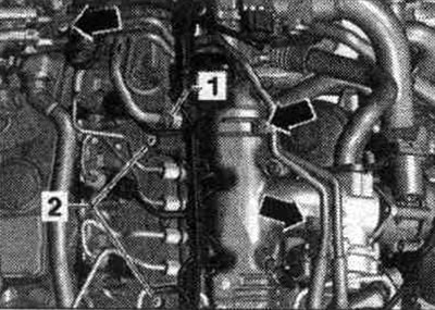
1. Intake manifold: with variable geometry intake manifold motor "V183" and variable geometry intake manifold position sensor "G513" (single component); disassembly is prohibited.
2. Bolt: 8 Nm.
3. Gasket: replace.
4. Lip seal: replace.
5. Connecting pipe: to the system radiator. exhaust gas recirculation.
6. Bolt: 20 Nm.
7. Gasket: replace.
8. Bolt: 10 Nm.
9. Intake manifold flap motor "V157": with throttle valve potentiometer "G69".
10/11. Bolt: 10 Nm.
12. Oil dipstick.
13. System valve. eGR "N18": with system potentiometer. exhaust gas recirculation "G212".
Take off
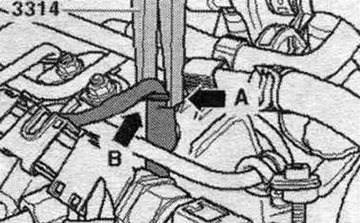
Remove the engine cover. Remove the cylinder head cover sound insulation. Disconnect glow plug connectors 5, 6, 7, and 8. Be careful not to damage the wiring when disconnecting the connectors, otherwise it will need to be completely replaced. When disconnecting the connectors, do not squeeze the pliers "3314" too hard, as this may damage the bushing.
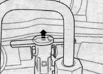
Use pliers "3314" with the groove "arrow A" on the flange of the sleeve "arrow B" and remove the connector from the spark plug.
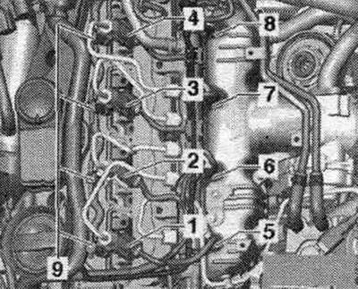
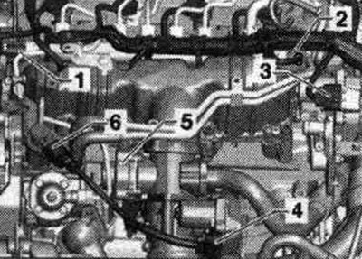
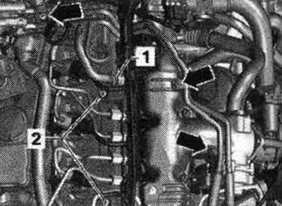
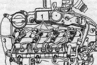
Remove the high-pressure fuel line "4" by unscrewing the union nuts of the high-pressure pump "1" and the fuel rail "5". Unscrew the bolts "arrows" of the high-pressure fuel line. Release the wiring harness "6".
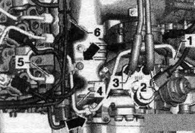
Disconnect both fuel lines. lines "2 and 3" from the high-pressure pump. Unscrew the "arrow" bolts securing both fuel lines.
Immediately close open connections with a special cap. Disconnect the following connectors.
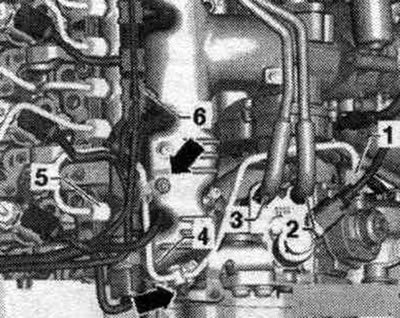
1. Fuel pressure sensor "G247". 2. Fuel pressure regulating valve "N276". 3. Servomotor of the variable geometry intake manifold "V183". 4. Motor of the flap in the intake manifold "V157". 5. Valve syst. exhaust gas recirculation "N18".
Open the air duct clamp "arrow" and remove it from the intake manifold flap motor "V157" in a downward direction. Unscrew the oil bracket bolt. dipstick. Remove the connecting tube of the system. eGR valve "N18". Unscrew the intake manifold mounting bolts crosswise from the outside inward. Remove the intake manifold.
Install
Installation in reverse order. Replace seals. Remove the intake manifold. Unscrew the oil bracket bolt. dipstick. Unscrew the intake manifold mounting bolts crosswise from the outside in.
Removal and installation the high pressure pump
Caution! Risk of damage to the high-pressure pump when running dry. Before starting the engine for the first time, fill the high-pressure pump with fuel. The high pressure pump must not run dry.
Remove the timing belt from the camshaft and high pressure pump. Disconnect the fuel metering valve connector "N290". Remove the high-pressure fuel line "4" by unscrewing the union nuts of the high-pressure pump "1" and the fuel rail "5". Unscrew the bolts "arrows" of the high-pressure fuel line.
Disconnect both fuel lines. lines "2 and 3" from the high-pressure pump. Unscrew the "arrow" bolts securing both fuel lines. Do not kink the fuel lines. Unscrew the belt pulley from the high pressure pump.
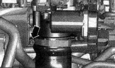
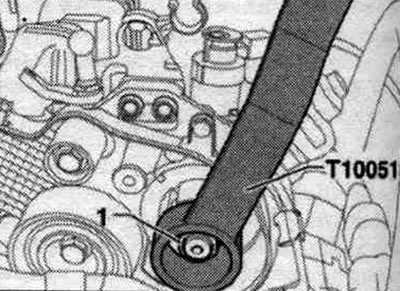
Hold the high-pressure pump bushing using the counter support "T10051" and unscrew the fastening nut "1".
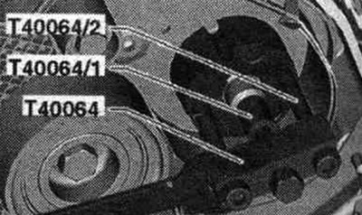
Install the puller "T40064" with the mandrel "T40064/1" and the pin "T40064/2", as shown in the figure, and remove the bushing from the high-pressure pump. If necessary, hold it with a 24 mm wrench to prevent it from turning.
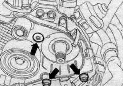
Unscrew the high pressure pump arrow mounting bolts. Carefully remove the fuel. high pressure pump.
Install
Installation in reverse order. Install the fuel injection pump timing belt. Install the fuel pump. high-pressure lines.
Caution! Before starting the engine for the first time, fill the high-pressure pump with fuel. The high-pressure pump must not be run dry. Dry running can cause damage to the high-pressure pump.
Adaptation of injectors
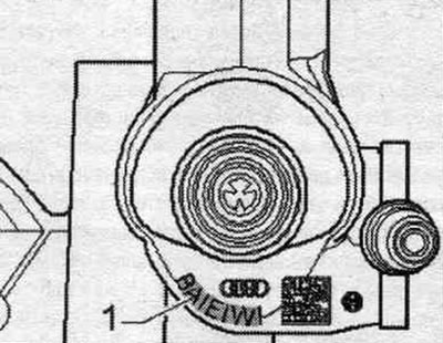
The function of "fuel quantity correction (1MA)" and "voltage correction (ISA)" is to adjust the volume of fuel injected individually for each cyl. common Rail system. Seven-digit correction values "1" (the data in the figure is for example purposes only) printed on each nozzle. Printed parameters can be alphabetic and/or numeric (ASCII-Code).
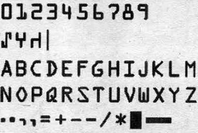
Symbol table for reading symbols on the injector
When updating an injector, the adaptation value of the new injector must be written into the engine control unit. When replacing an engine control unit, the corresponding "Injector injection volume base values" with "Injector base voltage (ISA)" must be entered into the new engine control units. Additionally, check the remaining injectors for "Fuel Quantity Correction (1MA)" with "Voltage Correction (ISA)" to ensure that all correction values are entered correctly. Once the correct matching parameters have been entered into the engine control unit memory, they must under no circumstances be entered again. The sequence of adjustments is described in "Guided Troubleshooting." (The procedure is also described in "Guided Functions.") Use the Tester for this.
Removal and installation injectors
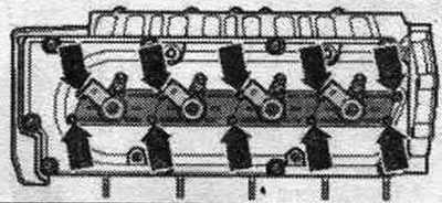
Remove the engine cover. Remove the sound insulation from the cylinder head cover. Mark the injector compatibility with the cylinder. Reinstallation is only permitted on the same cylinder. When working on the system. when injecting, observe the rules for maintaining cleanliness. Immediately close open connections with a special cap. Remove the return line pipes on the injectors by pressing both covers down and simultaneously pulling up the intermediate element to release the "arrow".
Disconnect connectors "1" from the injectors to be removed. Loosen the union nuts of the high-pressure lines using the "T40055" head on the injection modules. Loosen the union nuts of the high-pressure lines using a 17 mm open-end wrench "VAG 1331/6" on the fuel ramp.
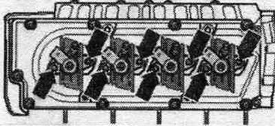
Unscrew the injector caps "arrows". Pull the caps upwards and turn them 90°. When unscrewing the injector mounting nuts, there is a risk of the nuts falling into the cylinder head. Work carefully to avoid unnecessary additional work. work or damage.
Loosen the clamps of the "arrow" injectors.
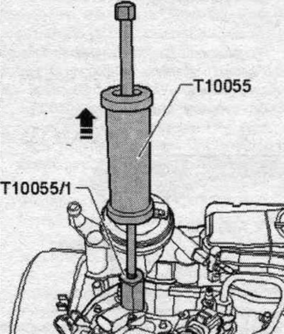
Install the "T10055" puller with the "T10055/1" adapter as shown and use a tapping motion to remove the injector in an upward direction. Place the removed injectors on a clean cloth.
Installing new injectors
When installing a new injector, it is necessary to replace: clamp, copper seal. ring, sealing ring of the injector socket, sealing ring of the return line fitting. When reusing high-pressure lines, observe the corresponding cylinder designations. High pressure lines can be reused after the following checks. Check the sealing cone of the corresponding high-pressure line for deformations and cracks. The hole must not be deformed or damaged. Lines with corrosion should not be reused.
Reinstalling injection nozzles
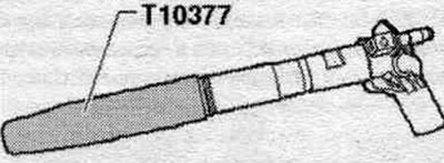
When reinstalling a used injector, the following must be replaced: clamp, copper seal. ring, sealing ring of the injector socket, sealing ring of the return line fitting. Apply rust remover spray to the injector needle. After about 5 minutes, remove any soot or oil particles with a rag. If the nozzle is heavily contaminated, its lower part should be additionally cleaned. clean with a soft brass brush to facilitate removal of the copper seal (do not allow the brass brush to come into contact with the injector nozzle channel). To remove the old copper gasket from the injector, carefully clamp the gasket in a vice so that it is clamped between the clamping jaws directly when turning. Using light twisting and pulling movements of your hand, remove the nozzle from the copper gasket. Use a scraper to clean off any deposits under the copper seal. ring. Risk of damage to the sealing surface of the injector. To remove soot particles from the injector sealing surface, clean the injector seat in the cylinder head with a rag soaked in oil or rust remover. Replace the seal. injector socket ring, use the mounting sleeve "T10377" for this. To avoid damaging the seal. rings put a new ring on the return line fitting, having previously lubricated it. Install the injectors. Tighten the high pressure fuel line union nuts by hand without tightening. Control the installation without stress.
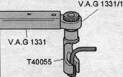
Use the VAG 1331 torque wrench with ratchet to tighten the high-pressure lines on the injectors "VAG 1331/1" and the socket wrench attachment "T40055".
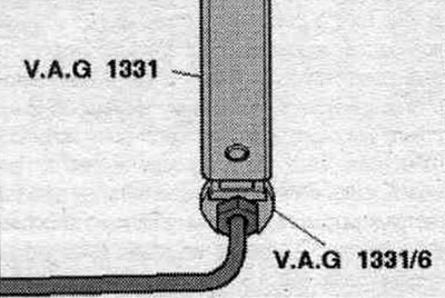
To tighten the high-pressure lines on the fuel distributor, use the torque wrench "VAG1331" and a 17 mm wrench "VAG 1331/6".
Observe tightening torque: installation of high-pressure fuel lines. Carefully install the connecting elements of the return lines onto the injector using the lip seal and applying pressure (pre-check the lip seal for damage). The lock should click into place, then gently press the release bolt down. After replacing one or more injectors, the ECU must perform a "Fuel Quantity Adjustment (IMA)" and "Voltage Adjustment (ISA)" for the new injectors. Additionally, check all other injectors to ensure that all matching parameters "Injector Performance Matching (IMA)" and "Injector Voltage Matching (ISA)" are entered correctly. If the correct matching parameters are entered into the engine control unit memory, they should not be re-entered under any circumstances.
Pump fuel. system and check for leaks
To remove air, do not open the high pressure outlets, air from the fuel. the system goes away on its own. Let the engine idle for a few minutes and then turn it off again. Turn off the ignition. Check all fuel. system and connection of return fuel. highways (4 pcs.) for leaks. If the seal is broken, despite the correct tightening torque, replace the faulty unit. Replacement of return lines is carried out only in a set with a pressure reducing valve. Carry out a test drive with at least one acceleration under maximum load and then recheck the high-pressure circuit for leaks. Presence of air in fuel. system during a test drive may cause the engine to operate in emergency mode. Turn off the engine and clear the fault memory. Continue with the test drive.
(The original version is on the portal: «AUDImanual.ru»)