Repair Chevrolet Repair Toyota Repair Honda Repair AvtoVAZ Repair Mercedes-Benz Repair BMW Repair Opel
Home  |  Contacts  |  Sitemap  |    
English Русский
Български
Беларускі
Український
Српски
Hrvatski
Română
Polski
Slovenský
Magyar
AudiManual.ru


  • AUDI 80
  • AUDI 100
  • AUDI A3
  • AUDI A4
  • AUDI A6
  • AUDI A8
  • AUDI Q
  • OTHER
  • ARTICLES
B8 (2007-2015) B7 (2004-2008) B6 (2000-2006) B6 (2000-2006, petrol) B5 (1994-2001) B5 (1994-2001, petrol)

Glow plugs, speed sensor, and Hall sensor — removal and installation (Audi A4 B8)

  • Home
  • Audi A4
  • B8 (2007-2015)
  • Power unit
  • Diesel engines 2.0 l (CA*)
  • Glow plugs, speed sensor, and Hall sensor — removal and installation
            0
Table of contents: Removal and installation glow plugs ↓ Removal and installation the engine… ↓ Removal and installation of the Hall… ↓

Removal and installation glow plugs


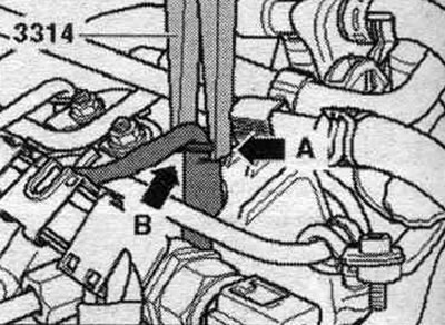
Turn off the ignition. Remove the engine cover. Remove the glow plug caps. Clean the glow plug channel in the cylinder head (no contaminants should enter the cylinder). Cleaning example: Remove heavy dirt with a vacuum cleaner. Spray brake cleaner or other suitable cleaner into the glow plug bore, leave it to act for a short time and blow it out with compressed air. Clean the glow plug channel with a rag soaked in oil. Be careful not to damage the wiring when disconnecting the glow plug connector; otherwise, it will need to be completely replaced. When disconnecting the plug connectors, do not squeeze the 3314 pliers, as this may damage the support sleeve. Install the pliers "3314" with the recess "arrow A" to the flange on the support sleeve "arrow B" and disconnect the connectors from the glow plugs.

Glow plug 1 «Q10» «5». Glow plug 2 «Q11» «6». Glow plug 3 «Q12» «7». Glow plug 4 «Q13» «8».

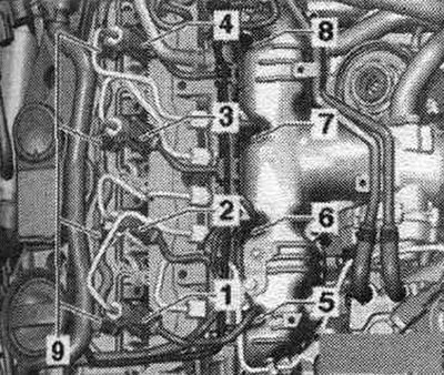
Glow plug 1 "Q10" "5". Glow plug 2 "Q11" "6". Glow plug 3 "Q12" "7". Glow plug 4 "Q13" "8".


Glow plug 1 «Q10» «5». Glow plug 2 «Q11» «6». Glow plug 3 «Q12» «7». Glow plug 4 «Q13» «8».


To unscrew the glow plugs, use a 10 mm "3220" swivel wrench.


Install


To tighten the glow plugs, use the 10mm "3220" swivel wrench in combination with a suitable torque wrench. Tighten the glow plugs to the specified torque. Tightening torque: 17 Nm. Attach the glow plug caps to the corresponding glow plugs and check the tightness of the connector connections. Install the engine cover.

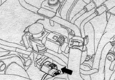
Removal and installation the engine speed sensor "G28"


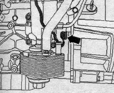
Remove the oil bracket. filter. Disconnect the connector from the engine speed sensor "G28" "arrow" using the mounting. tool "T10118". For removing the fixation of the electrical plug connection without installation. using the T10118 tool, press in the engine speed sensor plug with a screwdriver and simultaneously lift the release button with a thin bent wire.

Remove the oil bracket. filter. Disconnect the connector from the engine speed sensor «G28» «arrow»…


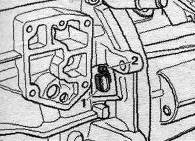
Release the wire. Unscrew the fastening screw "2" of the engine speed sensor "G28" "pos. 1".

Release the wire. Unscrew the fastening screw «2» of the engine speed sensor «G28» «pos. 1».


Install


Installation in reverse order. Install the oil bracket. filter.


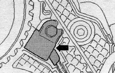
Removal and installation of the Hall sensor "G40"


Remove the poly V-belt. Remove the timing belt. Remove the vibration damper. Disconnect the Hall sensor plug connector "G40" "arrow". Detach the plug connector from the retainer.

Remove the poly V-belt. Remove the timing belt. Remove the vibration damper. Disconnect the Hall…


Unscrew the Hall sensor "G40" "arrow".

Unscrew the Hall sensor «G40» «arrow».


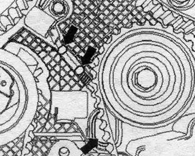
Remove the spacers with a screwdriver and remove the repair hole cover. Remove the G40 Hall sensor from the cylinder head and route the connector through the repair hole in the timing belt protective cover.

Remove the spacers with a screwdriver and remove the repair hole cover. Remove the G40 Hall sensor…


Install


Installation in reverse order. Close the repair hole in the timing belt protective cover with a rubber plug according to ETKA. Install the timing belt and adjust the timing.

[The original article is located on the online resource: AUDIMANUAL]
The article was checked by auto expert Timur Bazhenov
This article is available at russian, bulgarian, belarusian, ukrainian, serbian, croatian, romanian, polish, slovak, hungarian

Share information:
Previous articles
Audi A4 B8: Diesel engines 2.0 l (CA*)
Next articles

Exhaust gas recirculation (EGR) system — replacement of…
Exhaust system (EG) — replacement of components
Air flow meter, engine control unit and lambda probe — removal…
Intake manifold, fuel injection pump and injectors — replacement…


Similar articles on other Audi car models:
Fuel level sensor — removal and installation Audi 80 B3 (1986-1991, petrol)
Coolant Temperature Sensor — Removal and Installation Audi 100 C3 (1982-1990, diesel)
Removal and installation the fuel pump / fuel level sensor Audi A3 Type 8L (1996-2003)
Speedometer sensor — removal and installation Audi A6 C5 Allroad (1999-2005)
Engine speed sensor Audi A8 D2 (1994-2002)
Glow plugs, Hall sensor, engine speed sensor Audi Q5 Type 8R (2008-2017)
Removal and installation the oil pressure sensor Audi A2 (1999-2005)
Link to this page in different formats


Visitor comments

No comments yet


How much will 21 + 39 =


A4(B8, 2007-2015) 
  • General information
  • Operating instructions
  • Power unit
  • Petrol engines 1.8 l
  • Petrol engines 1.8/2.0 l
  • Petrol engines 3.0 l
  • Petrol engines 3.2 l
  • Fuel system (petrol)
  • Diesel engines 2.0 l (CA*)
  • Diesel engines 2.0 l (CJCB)
  • Diesel engines 2.7/3.0 l
  • Diesel engines 3.0 l
  • Fuel system (diesel)
  • Transmission
  • Manual gearbox 0B1
  • Manual gearbox 0B2
  • Manual gearbox 0B3
  • Manual gearbox 0B4
  • Automatic transmission 0B5
  • Automatic transmission 0B6
  • Automatic transmission 0AW
  • All-wheel drive system
  • Chassis
  • Front suspension
  • Rear suspension
  • Brake system
  • Steering system
  • Body
  • Exterior
  • Interior
  • Seats
  • Doors, locks and windows
  • Security system
  • Heating and air conditioning
  • Electrical equipment
  • Audio system
  • Power devices
  • Equipment and devices
  • Lighting and lamps
  • Electrical circuits
 
A4(B7, 2004-2008) 
  • General information
  • Introduction to manual
  • Troubleshooting
  • Operating instructions
  • Maintenance
  • Power unit
  • Petrol engines 2.0 (ALT)
  • Petrol engines 2.0 (TFSI)
  • Petrol engines 1.8 (MPI)
  • Diesel engines
  • Cooling system
  • Air conditioner
  • Fuel and exhaust system
  • Ignition system
  • Starting and charging
  • Transmission
  • Clutch
  • Manual gearbox
  • Automatic gearbox
  • Drive shafts
  • Chassis
  • Brake system
  • Front suspension
  • Rear suspension
  • Steering
  • Body
  • Exterior
  • Interior
  • Electrical equipment
  • Equipment and devices
  • Lighting and signaling
  • Windscreen wipers and washers
  • Electrical diagrams
  • Electrical diagrams (since 2007)
 
A4(B6, 2000-2006) 
  • General information
  • Vehicle Description
  • User manual
  • Maintenance
  • Power unit
  • Gasoline engine
  • Diesel engine
  • Lubrication system
  • Cooling system
  • Supply system
  • Injection system
  • Exhaust system
  • Ignition and control
  • Transmission
  • Gear box
  • Clutch and drive shafts
  • Chassis
  • Brake system
  • Car suspension
  • Steering
  • Body
  • Heating and ventilation
  • Exterior (external elements)
  • Interior (internal elements)
  • Electrical equipment
  • Power devices
  • Lighting and appliances
  • Electrical circuits
 
A4(B6, 2000-2006, petrol) 
  • General information
  • Introduction to the guide
  • Car care
  • Power unit
  • Engine repair
  • Lubrication system
  • Cooling system
  • Injection and control system
  • Ignition system
  • Power and exhaust system
  • Transmission
  • Clutch and drive shafts
  • Car gearbox
  • Chassis
  • Suspension and wheels
  • Steering
  • Brake system
  • Body
  • Interior
  • Exterior
  • Electrical equipment
  • Equipment and devices
  • Lighting and signaling
  • Power devices
  • Electrical circuits
 
A4(B5, 1994-2001) 
  • General information
  • Introduction to the guide
  • Car care
  • Maintenance (gasoline)
  • Maintenance (diesel)
  • Power unit
  • Gasoline engines
  • Diesel engines
  • Engine overhaul
  • Cooling system
  • Fuel injection (gasoline)
  • Fuel system (diesel)
  • Exhaust system
  • Ignition system
  • Transmission
  • Clutch
  • Mechanical gearbox
  • Automatic gearbox
  • Drive shafts
  • Chassis
  • Brake system
  • Car suspension
  • Steering
  • Body
  • Exterior
  • Interior
  • Doors, locks and windows
  • Heating and ventilation
  • Electrical equipment
  • Power devices
  • Equipment and devices
  • Electrical circuits
 
A4(B5, 1994-2001, petrol) 
  • General information
  • Vehicle description
  • Maintenance
  • Power unit
  • Engine repair
  • Turbocharging
  • Exhaust system
  • Cooling system
  • Ignition system
  • Fuel system
  • Motronic injection system
  • MPI and MPFI injection system
  • Transmission
  • Clutch
  • Gearbox and shafts
  • Chassis
  • Steering
  • Car suspension
  • Brake system
  • Wheels and tires
  • Body
  • Heating and ventilation
  • Body parts
  • Electrical equipment
  • Fuses and relays
  • Power devices
  • Lighting and lamps
  • Tools and devices
  • Electrical circuits
 
AudiManual.ru © 2017-2026 · Mobile version · Feedback · Sitemap: EN BG BY UA RS HR RO PL SK HU · Site search · News and articles
80 B2 · 80 B3 petrol · 80 B3 · 80 B4 · 100 C3 diesel · 100 C3 petrol · 100 C3 · 100 C4 petrol · 100 C4 · A3 Type 8L · A4 B5 petrol · A4 B5 · A4 B6 petrol · A4 B6 · A4 B7 · A4 B8 · A6 C4 · A6 C5 · A6 C5 Allroad · A8 D2 · Q5 Type 8R · Q7 Typ 4L · Audi A2 ·
This site uses cookies 🍪. Click the button to accept this fact.