
Table of contents: Exhaust system ↓ Diesel particulate filter suspension… ↓ Removal and installation the diesel… ↓ Exhaust manifold ↓ Removal and installation the exhaust… ↓
Exhaust system
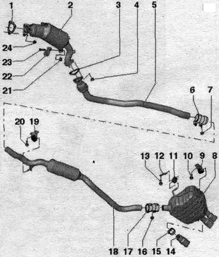
1. Gasket: replace.
2. Diesel particulate filter: with catalyst; with the pressure line of the exhaust gas pressure sensor 1 "G450"; after replacement, carry out adaptation in the "Guided functions" mode.
3. Gasket: replace.
4. Nut: replace; 23 Nm.
5. Downpipe: with detachable element; the detachable element must not be bent more than 10°. Risk of damage: Protect from impacts and shocks; align the system. exhaust gas release without mechanical stress.
6. Double clamp, front: align the system before tightening. exhaust gas outlet without mechanical stress; tighten the connections evenly.
7. Nut: 23 Nm.
8. Main muffler: factory installed with additional. the muffler is a single piece and can be replaced separately in case of repair; replace the muffler outlet pipe; align the system. exhaust gas release without mechanical stress.
9. Suspension mount: replace if damaged; check pre-tension.
10. Bolt: 20 Nm.
11. Fastening loop: replace if damaged.
12. Bracket.
13. Bolt: 23 Nm.
14. Exhaust pipe: replace separately during repair.
15. Clamp.
16. Nut: 23 Nm.
17. Rear clamp: for replacing the main and intermediate mufflers separately; align the system before tightening. exhaust gas outlet without mechanical stress; tighten the connections evenly.
18. Additional muffler: installed at the factory as one part with the rear mufflers, in case of repair it is replaced separately; align the system. exhaust gas release without mechanical stress.
19. Suspension mount: replace if damaged; check pre-tension.
20. Bolt: 23 Nm.
21. Nut: 23 Nm.
22. Bracket.
23. Bolt.
24. Nut: replace: lubricate with heat-resistant paste; 23 Nm.
Diesel particulate filter suspension elements
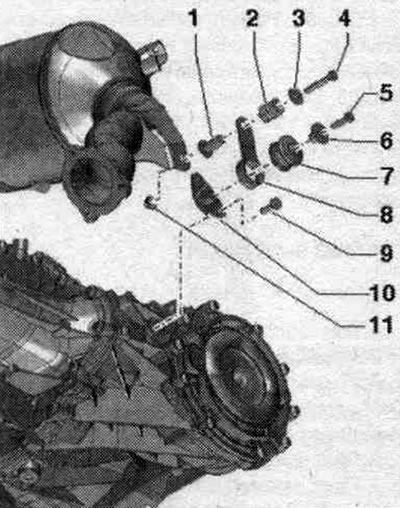
1. Expansion sleeve. 2. Pressure spring. 3. Disc. 4/5. Bolt. 23 Nm. 6. Spacer sleeve. 7. Buffer. 8. Pad. 9. Bolt. 23 Nm. 10. Bracket. 11. Nut.
Removal and installation the diesel particulate filter
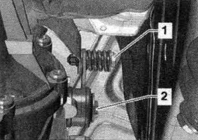
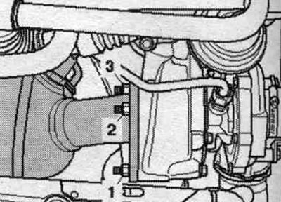
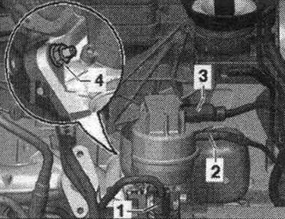
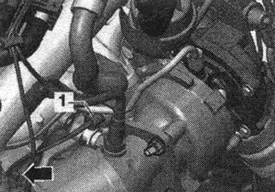
Remove the exhaust pipe. Disconnect bolt connection "1", unscrew bolt "2" and remove the diesel particulate filter suspension mount.
Unscrew the exhaust gas temperature sensor 4 "G648" "1". Remove the air duct housing. filter.
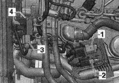
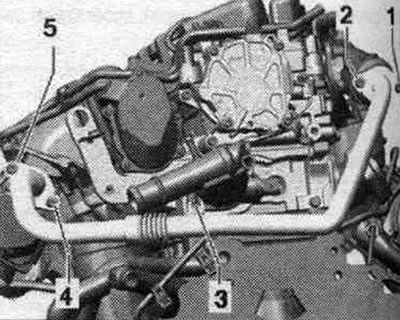
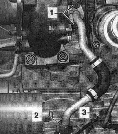
Remove the engine cover. Disconnect and release the connectors "1" of the lambda probe "G39" and "2" of the temperature sensor 3 "G495". Disconnect the connector "3" of the exhaust gas pressure sensor 1 "G450". Unscrew the bolt "4", release the air hoses of the exhaust gas pressure sensor 1 and unscrew them from the diesel particulate filter.
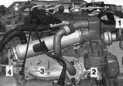
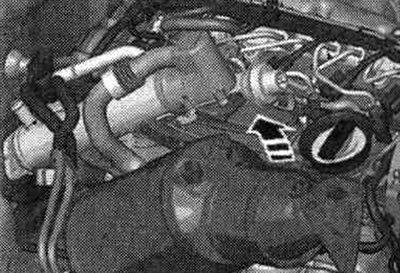
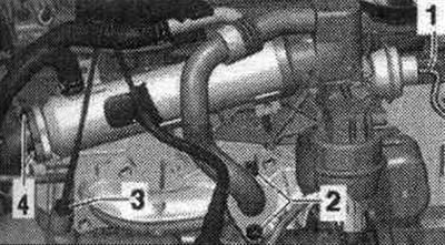
Unscrew the exhaust gas temperature sensor 3 "G495" "3". Remove the vacuum hose "1". Unscrew the bolts "2" and "4".
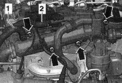
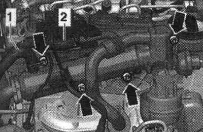
Do not unscrew lines "1" and "2". Unscrew the "arrow" bolts and tie up the system cooler. exhaust gas recirculation.
Unscrew the arrow bolts and remove the system bracket. exhaust gas recirculation.
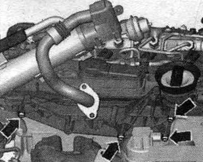
Unscrew nut "3" of the system pipe. eGR. Remove bolts "4" and "5" and move the EGR pipe to the side. System tube. eGR may not be removed.
In a car with an independent heater. Secure the coolant hoses to the end wall of the water drainage box using hose clamps up to 25 mm "3094" and remove them from the metal line. Loosen the coolant line on the shock absorber strut cup and side member and push it to the side. Unscrew nuts "1...3" on the turbocharger. In vehicles with independent heating, nut "1" is accessible from below.
Remove the particulate filter upwards "arrow".
Installation
Installation in reverse order. Replace all seals, gaskets and self-locking nuts. After replacing the particulate filter, carry out adaptation in the "Guided functions" mode.
Exhaust manifold
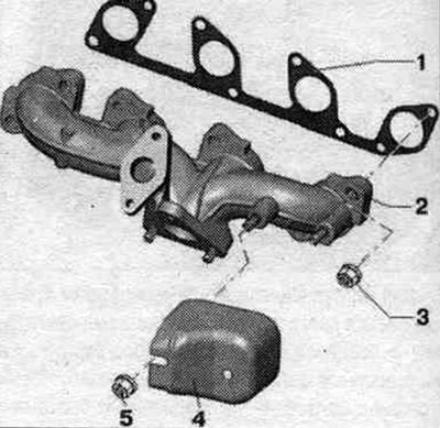
1. Gasket: replace. 2. Exhaust manifold. 3. Nut: 25 Nm; replace: install using mounting paste. 4. Thermal insulation shield. 5. Nut: 25 Nm.
Removing and installing the exhaust gas temperature sensor 1 "G235"
Remove sound insulation. Disconnect electrical connector "3" of exhaust gas temperature sensor 1 "G235" and disconnect it from the bottom of the engine block. Remove the air casing. filter.
Remove the engine cover "arrows". Remove the vacuum hose "1". Unscrew the bolts "2" and "4".
Do not unscrew lines "1" and "2". Unscrew the "arrow" bolts and tie up the system cooler. exhaust gas recirculation.
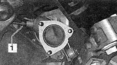
Unscrew the union nut "1".
Unscrew the exhaust gas temperature sensor 1 "G235" "1" and disconnect the wire on the cylinder block "arrow".
Installation in reverse order.
Removal and installation the exhaust gas temperature sensor 4 "G648"
Remove sound insulation. Remove the exhaust pipe. Support the gearbox using a tilter and a mounted gearbox support.
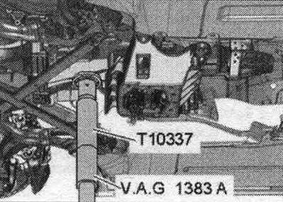
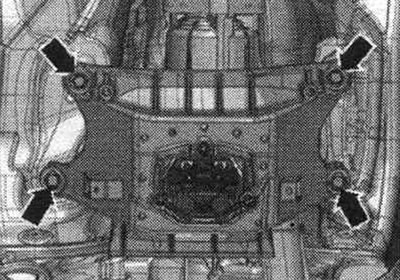
Unscrew the tunnel cross member arrow bolts.
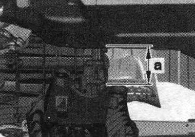
Lower the CP using a tilting device by the dimension "a". Dimension "a" = maximum 80 mm.
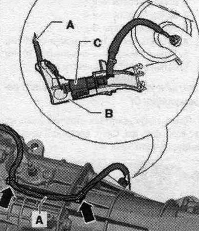
Unfasten the electrical wire "A" from the gearbox and disconnect the electrical connector "C". Disconnect the bracket "B" of the exhaust gas temperature sensor 4 "G648" from the gearbox.
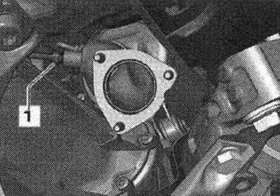
Unscrew the exhaust gas temperature sensor 4 "G648" "1".
Installation in reverse order.