
Fuel system
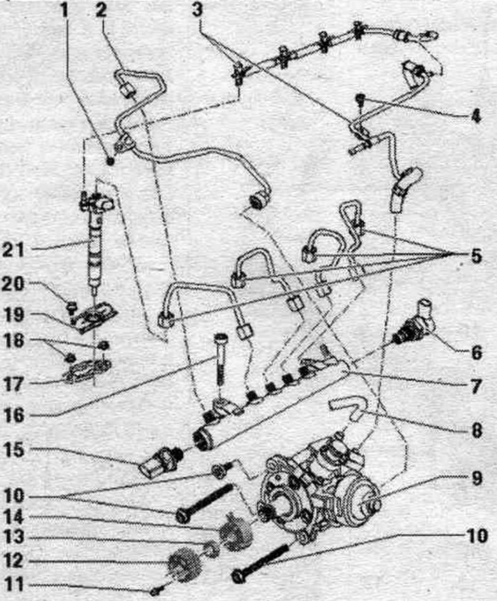
1. Bolt: 10 Nm.
2. High pressure line: 25 Nm; between the high pressure pump and the fuel. ramp.
3. Return fuel. highways: to the fuel tank; reverse fuel. the main line must not be bent, damaged or clogged; reverse fuel. do not disassemble the lines; they can only be replaced together with the pressure-reducing valve; the task of the pressure reducing valve is to maintain residual pressure in the return fuel. the main line pressure is always around 10 bar; this is necessary for the injectors to operate normally; after replacement, let the engine idle for two minutes to remove air from the fuel. system, then check the return fuel lines for leaks. highways.
4. Bolt: 10 Nm.
5. High pressure pipes: 25 Nm; between the fuel distributor and the injectors; do not change places; install freely.
6. Fuel pressure regulating valve "N276": 80 Nm; do not reuse.
7. Fuel rail.
8. Fuel supply. highway.
9. High pressure pump: with fuel metering valve "N290" (do not open) after replacement, the first fuel refueling should be performed. syst. (be sure to avoid working with fuel. dry system).
10. Bolt: 20 Nm: long bolts tighten 180°, short bolts tighten 90°.
11. Bolt: 20 Nm.
12. High pressure pump toothed belt pulley.
13. Nut: 95 Nm.
14. Hub: with sensor crown: use counter support "T10051" for unscrewing and tightening; to remove, use the "T40064" puller.
15. Fuel pressure sensor "G247": 100 Nm.
16. Bolt: 22 Nm.
17. Clamp: disassembled injectors and clamps to be assembled must be reinstalled in the cylinders exclusively in the same places; if the nozzle is replaced, the clamp must also be replaced.
18. Hexagonal flange nut of clamp bracket: 10 Nm.
19. System unit cover. injection.
20. Bolt: 5 Nm.
21. Injector: Removed injectors, high pressure lines and clamps that are reinstalled must be installed exclusively on the same place (cylinder).
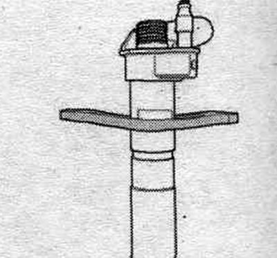
Clamp mounting position
(The original source of the article can be found on the website audimanual)