
Table of contents: Hose connection diagram without a… ↓ Connection diagram of hoses without… ↓ Wiring diagram for hoses with a… ↓ Wiring diagram for hoses with a… ↓ Draining and filling the coolant ↓ Cooling pump, thermostat, 4/2-way… ↓ Removal and installation the… ↓ Radiator and radiator fan ↓ Removal and installation the… ↓
CAUTION! Risk of burns from hot steam and hot coolant. When the engine is warm, the cooling system is under excess pressure. To relieve excess pressure, first close the expansion tank cap. tank with a rag and carefully open it.: When the engine is warm, the system. the cooling system is under pressure. If necessary, relieve pressure before performing repair work. Secure all hose connections with hose clamps of the appropriate series. For installation of spring clamps, it is recommended to use the hose clamp pliers "VAG 1921" or the hose clamp pliers "VAS 6340". Gaskets and seals. the rings need to be replaced. Arrows applied to the ends of the tubes and hoses of the system. cooling, must be located opposite each other.
Hose connection diagram without a 4/2-way valve (without autonomous heating)
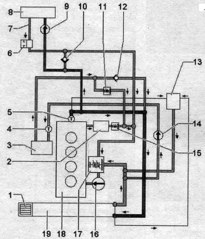
1. ATF radiator: not installed on vehicles with manual transmission.
2. Oil radiator.
3. Radiator system. exhaust gas recirculation.
4. Radiator outlet coolant temperature sensor "G83".
5. Coolant temperature sensor "G62".
6. Coolant supply shut-off valve: not always provided; depending on the date of manufacture and performance of the vehicle.
7. Ventilation hole.
8. Heat exchanger: after replacement, drain the old coolant and fill it with new coolant.
9. Coolant circulation pump "V50": installed only on vehicles with a start-stop system.
10. Check valve.
11. Thermostat with hoses.
12. Check valve.
13. Expansion tank: with cap.
14. Radiator pump system. exhaust gas recirculation "V400".
15. Thermostat with hoses: not always provided; depending on the date of manufacture and performance of the vehicle.
16. Coolant pump.
17. Thermostat.
18. Cylinder head/cylinder block: after replacement, drain the old coolant and fill it with new coolant.
19. Coolant radiator: after replacement, drain the old coolant and fill it with new coolant.
Connection diagram of hoses without 4/2-way
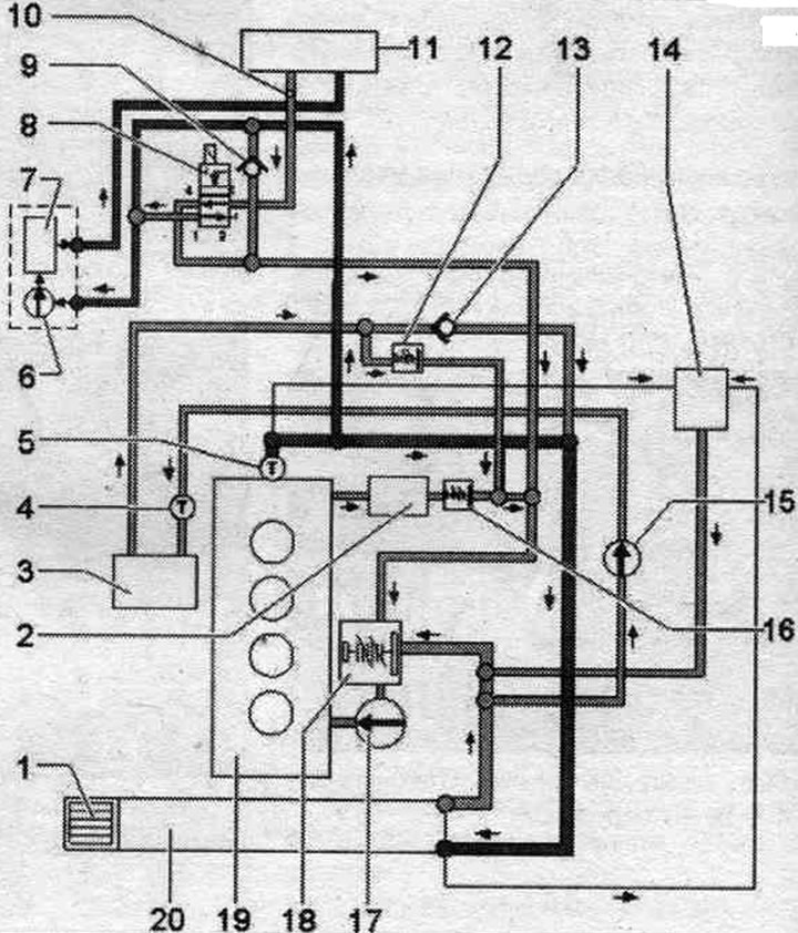
1. ATF radiator: not installed on vehicles with manual transmission.
2. Oil radiator.
3. Radiator system. exhaust gas recirculation.
4. Radiator outlet coolant temperature sensor "G83".
5. Coolant temperature sensor "G62".
6. Circulation pump "V55" (with autonomous heating).
7. Autonomous heater.
8. Heater coolant shut-off valve "N279".
9. Check valve.
10. Ventilation hole.
11. Heat exchanger: after replacement, drain the old coolant and fill it with new coolant.
12. Thermostat with hoses.
13. Check valve.
14. Expansion tank: with cap.
15. Radiator pump system. exhaust gas recirculation "V400".
16. Thermostat with hoses: not always provided; depending on the date of manufacture and performance of the vehicle.
17. Coolant pump.
18. Thermostat.
19. Cylinder head/cylinder block: after replacement, drain the old coolant and fill it with new coolant.
20. Coolant radiator; after replacement, drain the old coolant and fill it with new coolant.
Wiring diagram for hoses with a 4/2-way thermostatic valve (without autonomous heating)
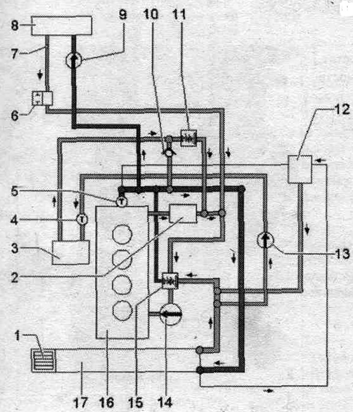
1. ATF radiator: not installed on vehicles with manual transmission.
2. Oil radiator.
3. Radiator system. exhaust gas recirculation.
4. Radiator outlet coolant temperature sensor "G83".
5. Coolant temperature sensor "G62".
6. Coolant supply shut-off valve: not always provided; depending on the date of manufacture and performance of the vehicle; control is carried out via the Climatronic "N422" coolant shut-off valve.
7. Ventilation hole.
8. Heat exchanger: after replacement, drain the old coolant and fill it with new coolant.
9. Coolant circulation pump "V50": installed only on vehicles with a start-stop system.
10. Check valve.
11. Thermostat with hoses.
12. Expansion tank: with cap.
13. Radiator pump system. exhaust gas recirculation "V400".
14. Coolant pump.
15. 4/2-way valve with thermostat: The thermostat is located inside the 4/2-way valve and cannot be replaced separately.
16. Cylinder head/cylinder block: after replacement, drain the old coolant and fill it with new coolant.
17. Coolant radiator: after replacement, drain the old coolant and fill it with new coolant.
Wiring diagram for hoses with a 4/2-way thermostatic valve (with autonomous heating)
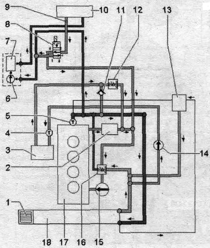
1. ATE radiator: not installed on vehicles with manual transmission.
2. Oil radiator.
3. Radiator system. exhaust gas recirculation.
4. Radiator outlet coolant temperature sensor "G83".
5. Coolant temperature sensor "G62".
6. Circulation pump "V55".
7. Autonomous heater.
8. Heater coolant shut-off valve "N279".
9. Ventilation hole.
10. Heat exchanger: after replacement, drain the old coolant and fill it with new coolant.
11. Check valve.
12. Thermostat with hoses.
13. Expansion tank: with cap.
14. Radiator pump system. exhaust gas recirculation "V400".
15. Coolant pump.
16. 4/2-way valve with thermostat: The thermostat is located inside the 4/2-way valve and cannot be replaced separately.
17. Cylinder head/cylinder block: after replacement, drain the old coolant and fill it with new coolant.
18. Coolant radiator: after replacement, drain the old coolant and fill it with new coolant.
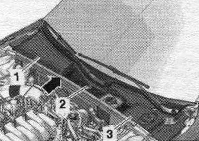
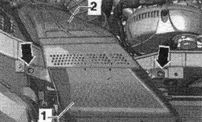
Draining and filling the coolant
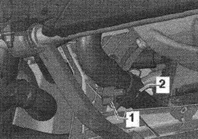
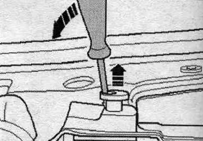
Open the expansion lid. tank. Remove the sound insulation. Place a service tray under the engine. Unscrew the drain plug "1" and drain the coolant. Ignore "Pos. 2".
Refueling
Note: The cooling system is filled with a coolant solution and coolant additives for the entire year. Other additives can significantly reduce the anti-corrosion effect. The resulting damage may lead to coolant leakage and, as a result, to serious engine damage. A coolant with the correct ratio of mixture components prevents the formation of corrosion and limescale. In addition, they increase the boiling point. Therefore, throughout the year in the system. concentrate must be present for cooling. Particularly in countries with tropical climates, the coolant's higher boiling point ensures reliable engine operation under high loads. The freezing point of the coolant must be at least -25°C. In countries with arctic climates, at least -35°C. Reducing the coolant additive content by topping up the coolant is prohibited, even during warm weather or when operating in countries with warm climates. The concentrate content should be at least 40%. If climatic conditions require the use of a coolant with a lower freezing point, the coolant additive content can be increased to 60% (coolant freezing point is -40°C). A different ratio will lower the freezing point of the coolant and, in turn, reduce its cooling effect. Use only clean drinking water to mix coolant. When replacing a radiator, heater heat exchanger, cylinder head, cylinder head gasket or cylinder block, reusing drained coolant is prohibited. To check the freezing temperature of the coolant, it is necessary to use the T10007 refractometer.
Ratio of components in coolant
- Additive (40%) and coolant (60%) to ensure a freezing temperature of -25°C.
- Additive (50%) and coolant (50%) to ensure a freezing temperature of -35°C.
- Additive (60%) and coolant (40%) to ensure a freezing temperature of -40°C.
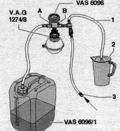
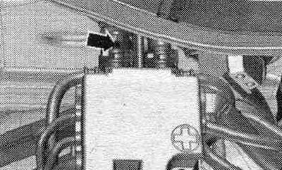
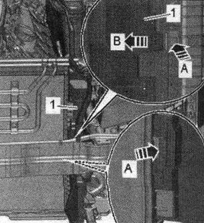
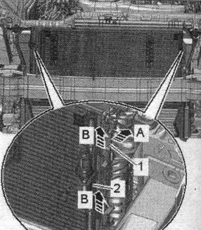
Close the drain plug "1". Pour 8 liters of coolant "VAS 6096", pre-mixed with the additive in the correct proportions, into the coolant reservoir. Screw on the system tester adapter. cooling "VAG 1274/8" to the expansion tank. Install the device for filling the system. cooling "VAS 6096" on the adapter "VAG 1274/8". Place outlet hose "1" into a small container "2". The exhaust air will capture a small amount of coolant, which must be collected. Close taps "A" and "B" by turning them perpendicular to the direction of flow. Connect hose "3" to the compressed air line. Pressure: 6...10 bar excess pressure.
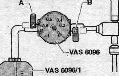
Open valve "B" by turning it in the direction of flow. In the cooling system, the ejector pump creates reduced pressure. The indicator arrow should move into the green field. Open tap "A" briefly, turning it parallel to the direction of flow so that the hose of the tank of the device for filling the system. the "VAS 6096" cooling system is full of coolant. Close valve "A" again. Open valve "B" for 2 minutes. The ejector pump continues to create a negative pressure in the cooling system. The indicator arrow should remain in the green field. Close valve "B". The indicator arrow should remain in the green field. In this case, low pressure in the system. cooling will be enough for its subsequent filling. If the arrow is below the green field, then you should repeat the previous operations. When the vacuum decreases, check the system. cooling for leaks. Remove the compressed air hose. Open tap "A".
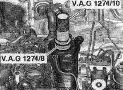
Due to the vacuum, the fluid coming out of the tank of the device for filling the system. cooling "VAS 6096" Coolant fills the system.. Remove the device for filling the system. cooling "VAS 6096" with adapter "VAG 1274/8" on expansion. tank. Attach the tube "VAG 1274/10" on the adapter "VAG 1274/8".
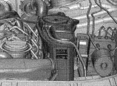
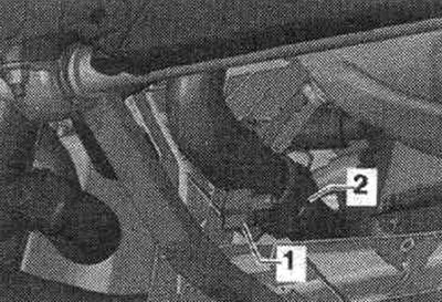
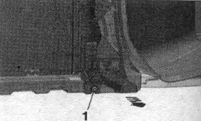
Unlock the clamps and remove the seal of the water drainage box "2". Ignore "pos. 1, 3" and the "arrow".
Unscrew the coolant hose to the heater heat exchanger and pull it back so that the ventilation hole in the coolant hose "arrow" is not closed by the connecting nipple. Fill the coolant until it starts to flow out of the coolant hose vent. Attach the coolant hose to the connecting fitting and tighten it.
On a vehicle with independent heating, turn on the heater for approx. for 30 seconds. Close the expansion tank lid. tank. Start the engine. Set the temperature to "HI" in all zones. Turn off the compressor by pressing the ECON button. Run the engine at 2000 rpm for 3 minutes. Let the engine idle until the two large coolant hoses on the radiator warm up. The engine should run at 2000 rpm for 1 minute. Turn it off and let the engine cool. Install the front noise insulation screen. Check the coolant level. When the engine is cold, the coolant temperature should be at the MAX mark. When the engine is warm, the coolant level should be above the MAX mark.
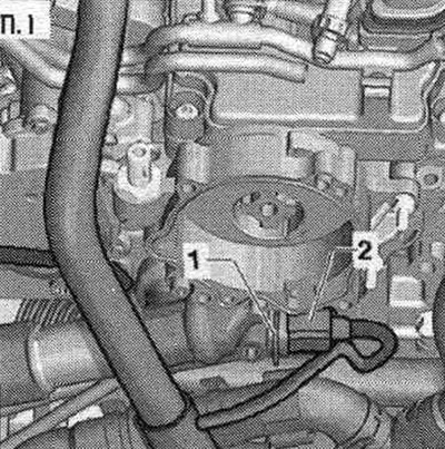
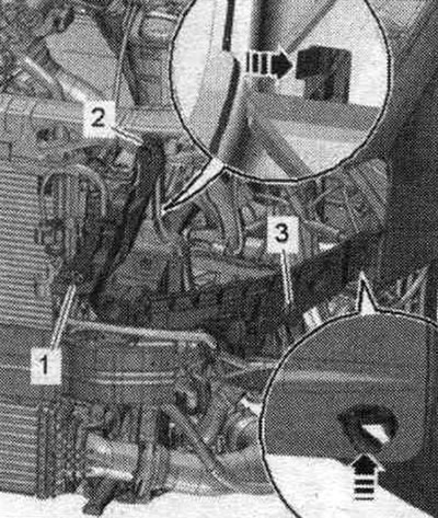
Removal and installation a 4/2-way valve with thermostat
The thermostat is located inside the 4/2-way valve and is not replaceable separately. Remove the "arrow" engine cover. Release the "arrow" hose clamps and remove the air duct hose.
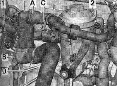
Disconnect connector "2". Unscrew nut "1" and put the bracket with the connector aside. Drain the coolant.
Remove the coolant hoses from the connecting pipes -A, B and D-. Unscrew bolt "2" with the XZN 8 "T10445" wrench. Unscrew bolts "1". Remove the valve from the cylinder block, remove the fitting "C" of the coolant pipe towards the left.
Cooling pump, thermostat, 4/2-way valve with thermostat
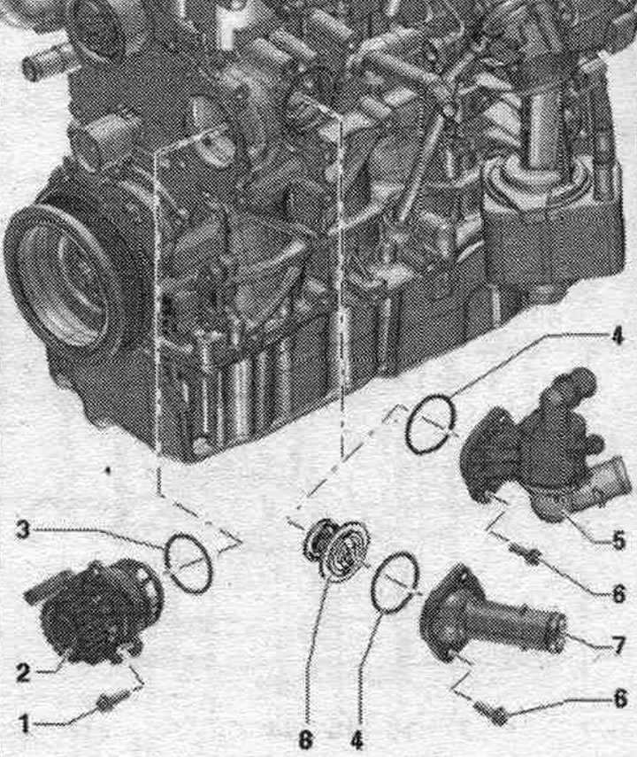
1. Bolt: 15 Nm.
2. Coolant pump.
3/4. O-ring: replace.
5. 4/2-way valve with thermostat: depending on the version; the thermostat is located inside the 4/2-way valve and is not replaceable separately.
6. Bolt: 15 Nm.
7. Connecting pipe: depending on the design.
8. Thermostat: installed only for versions with connecting pipes "7".
Installation
Installation in reverse order. Replace the seal. ring. Install the throttle module "J338". Install the generator.
Removal and installation the radiator pump system. exhaust gas recirculation "V400"
Remove the "arrow" engine cover. Release the "arrow" hose clamps and remove the air duct hose.
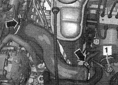
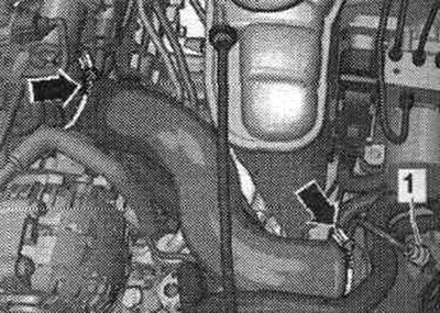
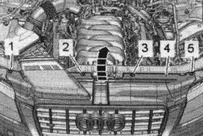
Disconnect the coolant hoses with clamps up to 25 mm "3094", as shown in the figure. Remove coolant hoses "2" and "3". Disconnect connector "4". Loosen bolt "1" and remove the radiator pump. eGR "V400" with bracket. Remove the radiator pump system. eGR from the bracket.
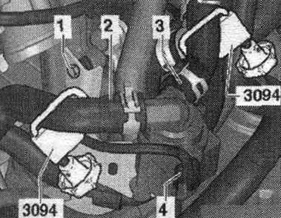
Installation in reverse order. Fill with coolant.
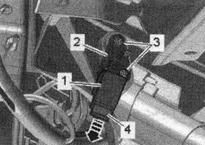
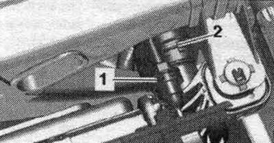
Removal and installation the radiator outlet coolant temperature sensor "G83"
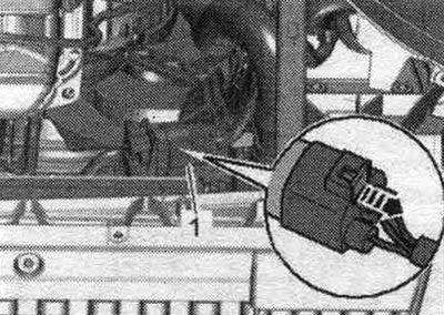
Remove the engine cover "arrows". Disconnect the plug connector "1" and unscrew the coolant temperature sensor at the radiator outlet "G83" "2".
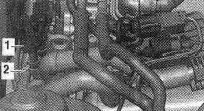
Installation in reverse order. Add coolant.
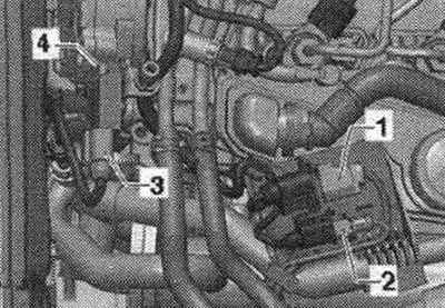
Removal and installation the coolant temperature sensor "G62"
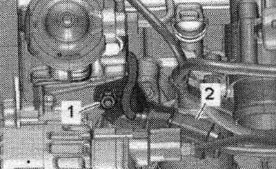
Remove the engine cover "arrows". Cold engine. Open the expansion tank cover briefly. tank for relieving residual pressure in the system. cooling. Unscrew bolt "4", unlock the air hoses of the exhaust gas pressure sensor 1.
Unscrew nuts "1" and remove holder "2". Remove the vacuum pump.
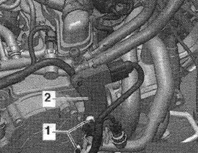
Disconnect plug "2" of coolant temperature sensor "G62". Remove retainer "1" of coolant temperature sensor "G62".
Installation
Installation in reverse order. Replace the seal. rings. To avoid coolant loss, insert the coolant temperature sensor "G62" into the hose. Check the coolant level.
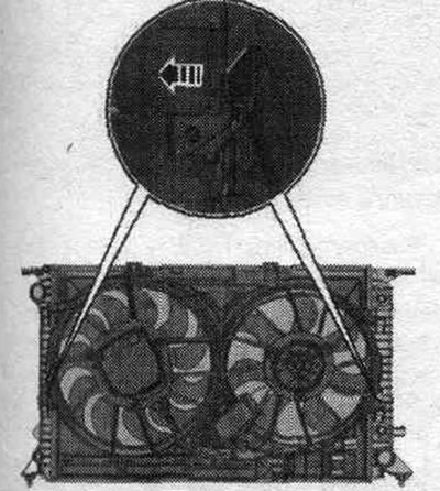
Radiator and radiator fan
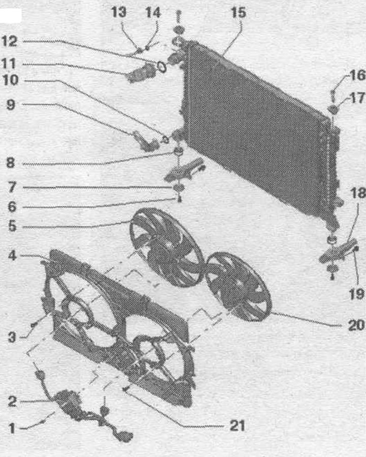
1. Bolt: 4.5 Nm.
2. Radiator fan control unit "J293".
3. Bolt: 5 Nm.
4. Fan frame.
5. Radiator fan "V7".
6. Bolt: 3.5 Nm.
7. Lining.
8. Rubber support: for radiator.
9. Cooling system hose: to remove, release the clamp.
10. Sealing ring: replace.
11. Cooling system hose: to remove, release the clamp.
12. Sealing ring: replace.
13. Cooling system hose: to expansion tank.
14. Sealing ring: replace.
15. Radiator: after replacement, drain the old coolant and fill it with new coolant into the cooling system.
16. Mounting bolts: Unlock with a screwdriver and remove.
17. Rubber buffer.
18. Radiator console.
19. Bolt.
20. Radiator fan 2 "V177": except for 400W fan control unit.
21. Bolt: 5Nm.
Connect the coolant hose to the coolant pipe using a fitting
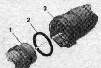
Remove the old seal. ring "2" from coolant hose "3". New seal. moisten the ring with concentrate and place it on the coolant hose. Push the coolant hose onto the coolant tube "1" until it clicks into place. Press the coolant hose in again and pull the hose to ensure that the coupling is properly secured.
Removal and installation the radiator together with the fan frame
The radiator and fan frame can only be removed and installed as an assembly. Even with proper installation, minor dents may appear on the fins of radiators and condensers. In this case, there is no talk of damage. Radiators or condensers should not be replaced due to such indentations. Remove sound insulation. Remove the front bumper trim and bumper. Remove the intercooler. Remove the right headlight. On vehicles with headlight washers, remove the right headlight washer nozzle. Disconnect connector "1" of the front passenger side airbag crash sensor "G284".
Unscrew bolts "1" and "2". Disconnect and remove the right headlight bracket "arrow".
Place a service tray under the engine. Unscrew the drain plug "1" and drain the coolant. Remove coolant hose "2" from the radiator by pressing the fastening clip.
Remove the electrical connector "1" of the radiator fan from the bracket by moving the lock back "arrow" and pressing the stopper down.
Remove the bolts "1, 2, 3, 5". Remove cover "4" of the radiator frame and hang it on the radiator grille "arrow".
Loosen the arrow bolts.
Remove the connecting fitting "1" and "2" from the radiator by loosening the clamp. Remove air duct "1" and intermediate flange "2".
Cars with multitronic gearbox: Install a device for pumping out and collecting oil under the disconnect point. Loosen the arrow bolts and disconnect the ATF lines from the radiator. To prevent ATF oil leakage, tie the ATF lines to the side member.
All
Release the clamps "arrow A" and remove the air duct "1" on the left and right "arrow B".
Release the radiator retainers on the left and right and remove them upwards "arrows".
Unscrew the bolts "1" on the left and right and remove the console and radiator from the radiator frame "arrow". Lower the radiator slightly.
The second mechanic should release the clamps "1" in the direction of "arrow A" and remove the condenser "2" upward from the radiator mounts "arrow B". Tilt the condenser forward with the hoses connected. Remove the radiator.
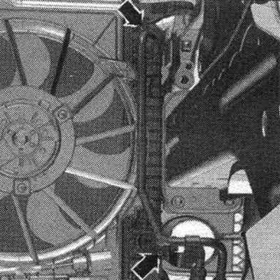
Press the locking tabs of the fan frame on the left and right "arrow" simultaneously and remove the fan frame from the radiator in an upward direction.
Installation
Installation in reverse order. Install the air duct of the intermediate flange of the air housing. filter. On vehicles with a multitronic transmission, attach the ATF lines. Install the intercooler. Install the bumper and front bumper cover. Connect the coolant hose to the coolant line using the fitting. Add coolant. If the radiator has been replaced, change the coolant. On vehicles with a multitronic transmission, check the ATF level.