
Table of contents: Oil sump, oil pump, balance shaft… ↓ Removal and installation of oil. pump ↓ Oil holder. filters and oil cooler ↓ Removal and installation the oil… ↓ Removal and installation of oil.… ↓ Checking the oil pressure and oil… ↓
Oil sump, oil pump, balance shaft block
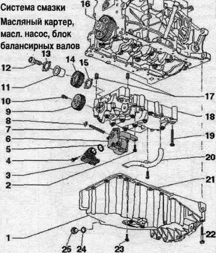
1. Oil pan.
2. Bolt: 10 Nm.
3. Suction pipe: if dirty, clean the mesh filter.
4. Bolt: 10 Nm.
5. Sealing ring: replace.
6. Oil pump: Before installation, check that both oil pump centering bushings are in place. pump on the balance shaft module.
7. Drive shaft oil. pump.
8. Retaining ring: should fit at the base of the groove; a damaged or overtightened retaining ring must be replaced.
9. Balance shaft gear.
10. Bolt: 20 Nm + 90°; replace.
11. Intermediate gear hub; replace.
12. Bolt: 90 Nm + 90°; replace.
13. Intermediate gear thrust bearing washer; replace.
14. Intermediate gear: replace; to achieve the required tooth profile clearance, the new intermediate gear is coated with a coating that ensures the correct clearance through wear; mounting position: Part number must be legible. When installing the intermediate gear, pay attention to the correct fit of the thrust bearing washer.
15. Intermediate gear thrust bearing washer; replace; take into account mont. position; if necessary, secure the intermediate gear to the housing with grease to install it.
16. Cylindrical gear: remove the gear from the crankshaft and fit a new gear.
17. Guide bushings: centering bushings of the balance shaft module on the cylinder block.
18. Balance shaft module: Install the reusable balance shaft module in place; before installation, check that both installation bushings for centering the balance shaft module on the cylinder block are in place.
19. Bolt: replace.
20. Oil intake pipe.
21. Bolt: 10 Nm.
22. Bolt: 40 Nm.
23. Bolt: 15 Nm; tighten in stages, crosswise.
24. Lip seal: replace.
25. Oil drain plug: 30 Nm.
Tightening sequence - 8-point balance shaft module
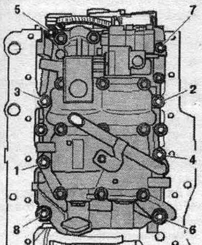
Tighten the balance shaft module bolts in the following order.
| Step | Bolts | Tightening torque/rotation angle |
| 1 | "1...8" | tighten by hand in the sequence. |
| 2 | "1...8" | pre-tighten in sequence, torque 6 Nm |
| 3 | "1...4" | tighten to 20 Nm |
| 4 | "5" | tighten to 13 Nm |
| 5 | "6" | tighten to 20 Nm |
| 6 | "7" | tighten to 13 Nm |
| 7 | "8" | tighten to 20 Nm |
| 8 | "1...8" | tighten with a rigid wrench by 90° in sequence. |
Tightening sequence - 6-point balance shaft module
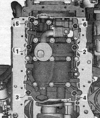
Tighten the balance shaft module bolts in the following order.
| Step | Bolts | Tightening torque/rotation angle |
| 1 | "1...6" | tighten by hand in the sequence. |
| 2 | "1...6" | pre-tighten the bolts in sequence. torque of 6 Nm |
| 3 | "1...4" | tighten to 20 Nm |
| 4 | "5 and 6" | tighten to 13 Nm |
| 5 | "1...6" | tighten with a rigid wrench by 90° in sequence. |
Oil level and temperature sensor "G266"
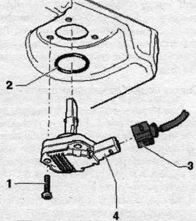
1. Bolt: 9 Nm. 2. Sealing ring; replacement. 3. Electrical connector. 4. Oil level and temperature sensor "G266".
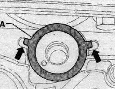
Mounting position of thrust bearing washer
Make sure that the thrust bearing washer "A" does not slip out of the recesses of the balance shaft module "arrow" when installing the intermediate gear and does not become jammed as a result. If necessary, secure with grease on the balance shaft module.
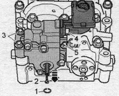
Removal and installation of oil. pump
Remove the oil pan. Remove snap ring "1" using a snap ring collet. Screw in the M3 "2" bolt and remove the drive shaft from the oil. pump "arrow". Unscrew bolt "4" and remove the suction pipe from the oil. pump. Unscrew bolts "3" and "5" and remove the oil pump. pump. Do not loosen the intermediate gear bolt.
Installation
Installation in reverse order. Replace the seal. ring. A damaged or overtightened retaining ring must be replaced. The retaining ring must fit into the base of the groove. Before installing the oil. check the presence of both mounting bushings on the pump. Install the oil pan.
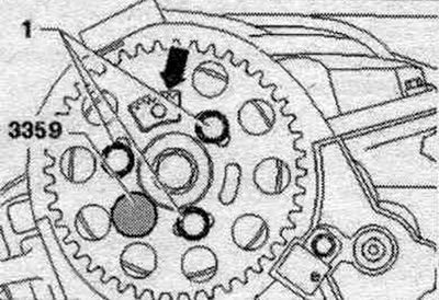
Removal the balance shaft module
Release the arrow clamps and remove the timing belt protective cover. "Pos. 1" should not be taken into account. Risk of damage due to slipping toothed belt. Turn the crankshaft only in the direction of engine rotation. Rotate the crankshaft using the timing belt bolt until the camshaft is at TDC. Secure the camshaft hub with the fuel pump locking pin. direct injection diesel engine "3359". The toothed segment "arrow" should point upward. Remove the oil pan.
Balance shaft module with 8 threaded connections
Unscrew the bolts in sequence. "8...1" and remove the balance shaft module with the oil pump.
Balance shaft module with 6 threaded connections
Unscrew the bolts in sequence. "6...1" and remove the balance shaft module with the oil pump.
Installing a new balance shaft module
When installing, ensure correct lateral clearance in the gear engagement of the balance shaft module drive. To achieve the required tooth profile clearance, a coating is applied to the new intermediate gear. At the beginning of operation, this coating quickly wears off, thereby ensuring the establishment of the required lateral clearance. Therefore, when installing a new balance shaft assembly, a new intermediate gear with a suitable coating must always be installed. Bolts tightened at the tightening angle should be replaced.
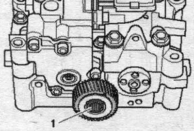
To install the balance shaft module, it is necessary to loosen the intermediate gear bolt connection. In this case, make sure that the bolt is not too loose to avoid the bearing washer falling out behind the intermediate gear. Before installing the balance shaft module on the cylinder block, loosen the intermediate gear bolt "1" approx. 45°. Make sure both mounting bushings are present to properly position the balance shaft module on the cylinder block. In this case, do not allow damage to the coating of the intermediate gear.
Tighten the balance shaft module with 8 threaded connections. Tighten the balance shaft module with 6 threaded connections. Fix the balance shaft using the locking device "T10255" and rotate the shaft if necessary. The journal of the locking device must enter the groove of the balance shaft.
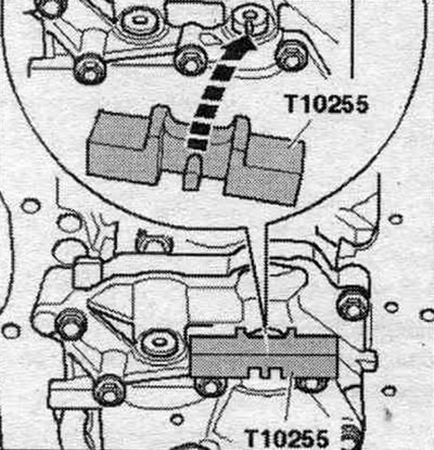
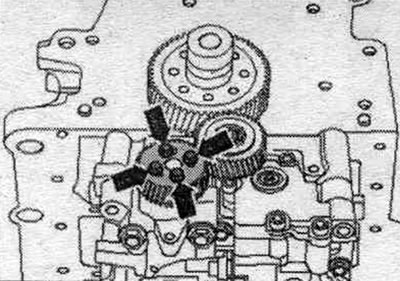
Carefully place the gear onto the balance shaft. At the same time, slightly push the intermediate gear to the side. In this case, the threaded holes of the balance shaft should be located, if possible, exactly in the middle of the concentric grooves of the gear wheel. If the longitudinal holes in the balance shaft gear do not match the threaded holes, it is necessary to turn the gear by the corresponding number of teeth and re-install it. Attach the balance shaft gear "arrow". Remove the locking device "T10255".
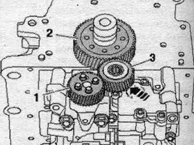
The following 3 stages of work must be completed simultaneously (need help from 2 mechanics). Press intermediate gear "3" firmly, using a wooden block if necessary, in the direction of the arrow, into the gear mesh between gear "2" and balance shaft gear "1". At the same time, slightly turn the balance shaft gear counterclockwise. Tighten the new idler gear bolt. After installation, there should be no play in the intermediate gear. This can be checked manually without much effort.
Installation in reverse order. Install the oil pan.
Installation of a previously used balance shaft block
When loosening the idler gear bolt, replacing the drive gear on the crankshaft, or removing the crankshaft, the coated idler gear and hub, including the balance shaft bolt and washer, must be replaced. Otherwise, the lateral clearance in the gear engagement will not comply with the norm. If the balance shaft module is reused, replacing the crankshaft pinion and removing the crankshaft is not performed, proceed as follows. Under no circumstances should the intermediate gear be unscrewed. Bolts tightened at the tightening angle should be replaced. Fix the balance shaft* using the locking device "T10255", if necessary, rotate the shaft. The journal of the locking device must enter the groove of the balance shaft. Ensure that both alignment bushings are present to properly position the balance shaft module on the cylinder block. Install the balance shaft module onto the cylinder block. With the balance shaft locked, the intermediate gear must engage with the drive gear on the crankshaft. The intermediate gear should have a noticeable play in rotation. Tighten the balance shaft module with 8 threaded connections. Tighten the balance shaft module with 6 threaded connections. Installation in reverse order. Install the oil pan.
Oil holder. filters and oil cooler
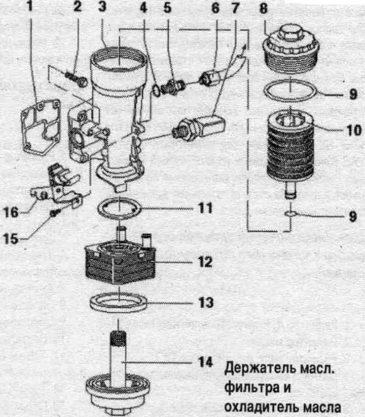
1. Gasket: replace.
2. Bolt: 15 Nm + 90°; replace; install the top left and bottom right screws first, then the rest, and then tighten all four crosswise.
3. Oil holder. filters: Check for free space with adjacent parts.
4. Lip seal: replace.
5. Connecting pipe: 30 Nm.
6. Oil supply line: 22 Nm; going to the turbocharger.
7. Oil pressure sensor "F1": 22 Nm; marking: brown: 0.7 bar; if there is a leak, bite and replace the seal. ring.
8. Cover: 25 Nm.
9. Sealing ring: replace.
10. Oil element. filter: Follow the instructions.
11. Lip seal: replace; lubricate before installation; insert into the protrusions on the oil radiator.
12. Oil radiator: check for free space with adjacent parts.
13. Lip seal: replace.
14. Screw plug: 25 Nm.
15. Bolt: 10 Nm.
16. Bracket: for wiring harness.
Mounting position of oil cooler gasket
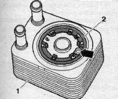
Place gasket "2" so that it can be secured to all journals of oil cooler "1". The oil hole "arrow" must not be blocked by the gasket.
Removal and installation the oil holder. filter
Remove the engine cover. "arrows". Release the "arrow" hose clamps and remove the air duct hose. Drain the coolant.
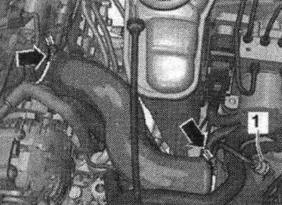
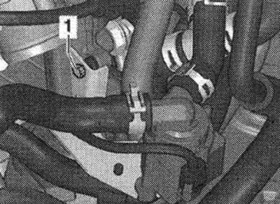
Remove the coolant hoses "arrows". Unscrew the bolts "1" and "2", remove the coolant tube.
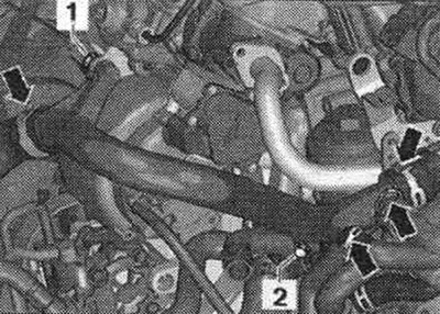
Unscrew bolts "1" and "2". Unscrew cover "3" and remove the oil filter element. filter.
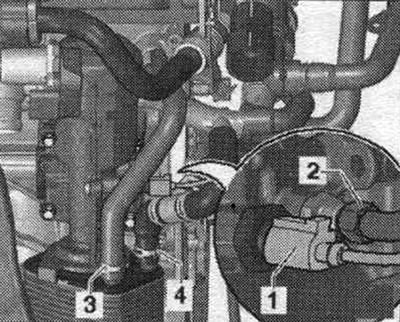
Disconnect connector "1". Unscrew the oil supply line "2". Remove coolant hoses "3" and "4".
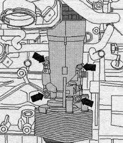
Unscrew the arrow bolts and remove the oil bracket. filter.
Installation
Installation in reverse order. Fill with coolant. Check the oil level.
Removal and installation of oil. engine radiator
Remove sound insulation. Remove the "arrow" engine cover. Release the "arrow" hose clamps and remove the air duct hose. Unscrew cover "3" and remove the oil filter element. filter. Unscrew bolt "1" and unscrew the radiator system pump. circulation of the exhaust gas "V400" to the side.
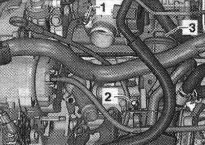
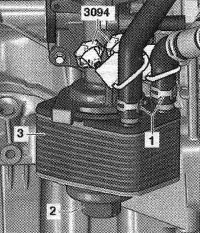
Disconnect the coolant hoses with clamps up to 25 mm "3094", as shown in the figure. Remove coolant hoses "1". Unscrew the screw plug "2", remove the oil radiator "3".
Installation
Installation in reverse order. Fill with coolant. Check the oil level.
Checking the oil pressure and oil pressure sensor
Checking the oil pressure sensor
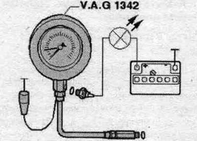
The oil level is normal. Oil temperature not less than 80°C (the radiator fan should turn on at least once). Remove the oil pressure sensor "F1" - brown insulation - and screw it into the control device. Screw the pressure tester into the oil pressure holder. filter instead of a sensor. Connect the brown wire of the pressure gauge to ground (-). Connect the voltage tester -VAG 1527B- using the auxiliary cable. wires from -VAG 1594 A- to the positive terminal of the battery (+) and the oil pressure sensor. The tester LED should not light up. Start the engine and slowly increase the speed. At 0.55...0.85 bar excess pressure the LED should light up, otherwise replace the oil pressure sensor.
Checking oil pressure
Oil pressure at idle: minimum 0.8 bar. Oil pressure at 2000 rpm: minimum 2.0 bar.