
Table of contents: Cylinder head cover ↓ Cylinder head ↓
Cylinder head cover
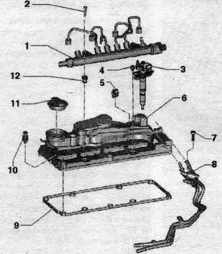
1. High pressure fuel tank (ramp element): with system tubes. fuel injection; do not change the curved shape of the system tubes. fuel injection.
2. Bolt: 22 Nm.
3. Injection module (piezo injector).
4. Bolt.
5. Clamp.
6. Cylinder head cover.
7. Bolt: 10 Nm.
8. Fuel lines.
9. Gasket: replace if damaged or leaking.
10. Bolt: observe the tightening sequence.
11. Lid.
12. Bushing: fuel fastening. ramps (Rail); if damaged, replace.
Disconnecting the cylinder head cover
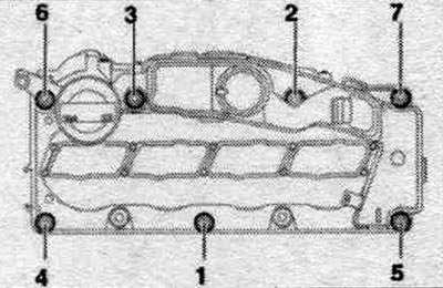
1. Loosen the nuts in sequence. "7...1".
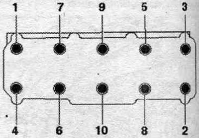
Tightening sequence of cylinder head cover bolts
2. Tighten the bolts by hand in several stages in sequence. "1...7".
3. Tighten the bolts in sequence. "1...7" with a torque wrench set to 10 Nm. Ensure that the cylinder head cover is not tilted.
Removal
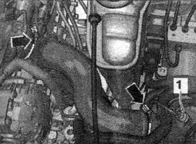
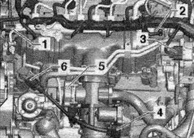
Remove the "arrow" engine cover. Remove the injector noise-insulating cover. Remove the injectors. Remove the fuel rail. Release the arrow clamps and remove the timing belt protective cover. Remove bracket "1" with the wiring for the lambda probe and the temperature sensor in front of the diesel particulate filter from the cylinder head cover. Move and release the crankcase ventilation "3.".
Loosen the fuel bolts. highways "arrows".
Unscrew bolts "1...7" and remove the cylinder head cover.
Installation
Installation in reverse order. Replace bolt seals if damaged. Install the cylinder head cover, tightening screws.
Cylinder head
The included plastic spacers protecting the exposed valves should only be removed immediately prior to installing the cylinder head. When replacing the cylinder head, the coolant should also be changed.
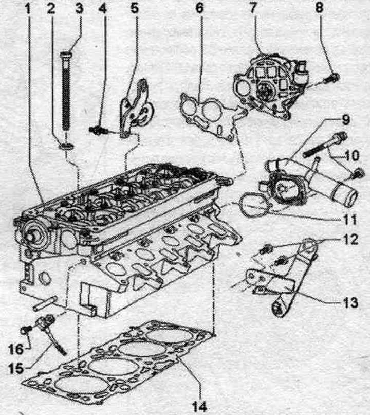
1. Cylinder head: after replacement, drain the old coolant and fill it with new coolant into the cooling system.
2. Disc: for cylinder head bolt.
3. Cylinder head bolt: observe the sequence when loosening, observe the sequence when tightening; before installation, install washers in the cylinder head.
4. Bolt: 25 Nm.
5. Hanging eye.
6. Gasket: replace.
7. Vacuum pump.
8. Bolt: 10 Nm.
9. Coolant connection nipple.
10. Bolt: 10 Nm.
11. Gasket: replace.
12. Bolt: 25 Nm.
13. Hanging eye.
14. Cylinder head gasket: replace; observe markings; after replacement, drain the old coolant and fill it with new coolant into the cooling system.
15. Hall sensor "G40": for camshaft position; to remove and install, you need to remove the toothed belt from the camshaft gears and unscrew the idler pulley.
16. Bolt: 10 Nm.
Disconnecting the cylinder head
Loosen the cylinder head bolts in sequence. "1...10".
Cylinder head bolt tightening sequence
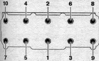
1. Tighten with a torque wrench to 40 Nm. 2. Tighten with a torque wrench to 60 Nm. 3/4. Tighten 90° further with a regular wrench. Tightening the cylinder head mounting bolts after repair work is not necessary.
Cylinder head seal markings
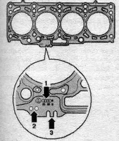
1. Parts catalog number. 2. Holes. 3. Not taken into account.
Note: If different piston protrusions are obtained, the largest size should be used for shim selection. The thickness of the cylinder head seal to be installed depends on the piston protrusion. When replacing, install a seal with the identical marking "arrow 2".
Removal and installation the cylinder head
Disconnect the battery. Drain the coolant. Remove the air intake manifold. filter. Remove the system radiator. eGR. Remove the turbocharger. Remove the timing belt. Remove the cylinder head cover. Remove the exhaust pipe. Release the "arrow" hose clamps and remove the air duct hose. Remove the dipstick guide tube from the throttle body.
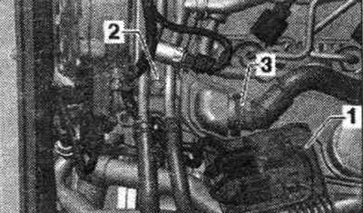
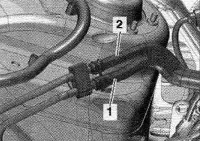
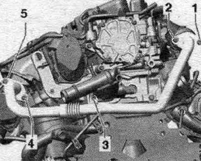
Disconnect the supply "1" and return "2" fuel lines.
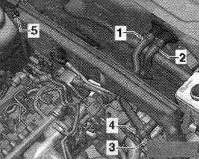
Remove coolant hoses "3" and "4".
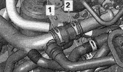
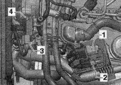
Remove hose clamps "1" and "2", disconnect the coolant hose.
Unscrew nut "3" of the system pipe. eGR. Remove bolts "4" and "5" and move the EGR pipe to the side. Unscrew the bolt on the cylinder head of the pressure oil line going to the turbocharger. System tube. eGR may not be removed.
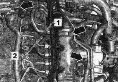
Unscrew bolt "4", unlock the air hoses of the exhaust gas pressure sensor 1.
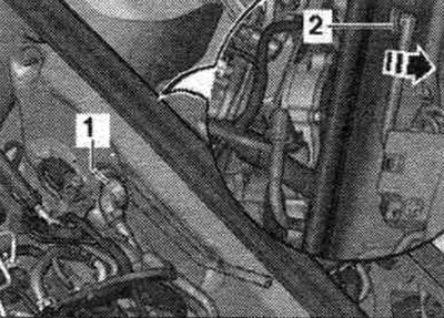
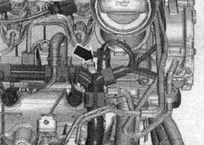
Remove the vacuum pipe "1" from the end wall of the water drainage box; to do this, disconnect the vacuum hose "2" on the rear side of the "arrow".
Disconnect the following plug connectors.
3. Variable geometry intake manifold servomotor "V183". 4. Intake manifold flap motor "V157". 5. System valve. exhaust gas recirculation "N18".
Unscrew the camshaft timing belt pulley and remove the camshaft hub using the T10052 puller. Loosen the timing belt cover mounting bolt. Unscrew the timing belt tension roller mounting nut. Unscrew the Hall sensor bolt "G40" "arrow", put the Hall sensor "G40" aside.
Loosen the cylinder head bolts in sequence. "1...10". A second mechanic is required to remove the cylinder head. The timing belt tensioner pulley is removed from the locating pin when removing the cylinder head. First lift the cylinder head from the gearbox side and remove it from the timing belt cover. Make sure that the timing belt tension roller does not fall out.
Installation
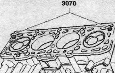
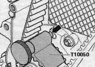
Installation in reverse order. Always replace the cylinder head bolts. When repairing, carefully remove any remaining sealant from the cylinder head and cylinder block. Avoid creating long scratches or burrs. Carefully remove any remaining sandpaper and grinding material. The new cylinder head gasket should be removed from the packaging immediately before installation. The gasket must be handled with great care. Damage to the silicone layer and corrugated connections leads to loss of tightness. Before installing the cylinder head, remove the crankshaft locking tool "T10050" and rotate the crankshaft counterclockwise until all pistons are evenly positioned below TDC. Install the cylinder head gasket with the marking facing up. For centering, screw the guide bolt "3070" into the outer holes on the suction side.
When installing the cylinder head, the tension roller must be placed on the mounting bolt. Place the cylinder head on, insert the remaining 8 cylinder head screws and tighten by hand. Using a screwdriver, remove the guide bolt from the 3070 through the screw holes and install the cylinder head bolts. Tighten the cylinder head in four stages. Secure the rear timing belt cover to the cylinder head. Install the hub and camshaft gear. Secure the camshaft and high-pressure pump using the 3359 unit injector locking pin. Rotate the crankshaft in the direction of engine rotation to TDC and secure it with the T10050 crankshaft locking tool. Install the timing belt.
Installation in reverse order. Install the cylinder head cover. Install the poly V-belt. Fill with coolant.
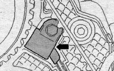
Compression check
Oil temperature approx. 80°C. Battery voltage minimum 12.5 V. Remove the engine cover "arrows". Disconnect the plug connector of the fuel pressure regulating valve "N276" "arrow" on the fuel distributor.
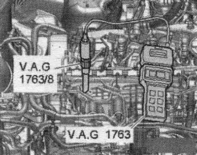
To relieve pressure in the fuel. turn on the engine briefly on the ramp. Remove all glow plugs. Screw in the adapter "VAG 1763/8" instead of the corresponding glow plug and connect the compression pressure gauge "VAG 1763".
The second mechanic should crank the starter until the compression gauge stops showing an increase in pressure. Conduct a check of each cyl..
| Compression values | Bar of excess pressure |
| New | 25,0...31,0 |
| Maximum tolerance | 19,0 |
| Maximum difference between cylinders | 5,0 |
Installation
Installation in reverse order. Install glow plugs. Since the plug connectors were removed while the engine was running, the following entry was saved in the engine control unit fault memory: Interrogate the fault memory in the vehicle self-diagnosis mode.