Table of contents: Sealing flange and driven disc ↓ Replacing the rear seal. flange ↓ Pistons and connecting rods ↓ Crankshaft ↓ Removal the timing gear from the… ↓
Sealing flange and driven disc
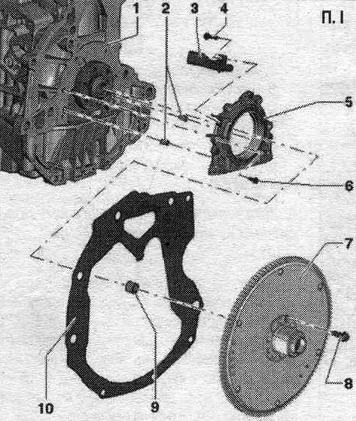
1. Cylinder block.
2. Guide bushings.
3. Engine shaft speed sensor "G28".
4. Bolt: 4.5 Nm.
5. Sealing flange with lip seal: with speed sensor ring; replace only as a set; working edge of the lip seal add. do not lubricate; before installation, remove any remaining oil from the crankshaft journal with a clean rag; for installation, use the support sleeve included in the delivery kit.
6. Bolt: 15 Nm.
7. Drive disc: To loosen the bolts, secure with 3067.
8. Bolt: 60 Nm + 90°; replace.
9. Needle bearing.
10. Spacer: suspended from the flange; must be installed on mounting bushings; do not damage/bend during installation work.
Install the intermediate shield
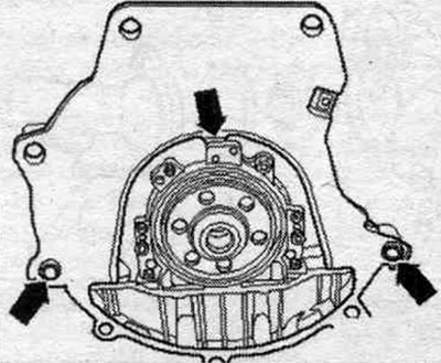
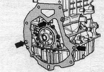
Hang the intermediate shield on the seal. flange and place it on the mounting bushings of the "arrow".
Replacing the rear seal. flange
Pressing out the seal. flange with sensor ring
Dismantle the gearbox. Remove the driven disk. Place an oil drainer under the engine and drain the oil. Remove the intermediate plate. Set the crankshaft to the TDC position as indicated. Remove the oil pan.
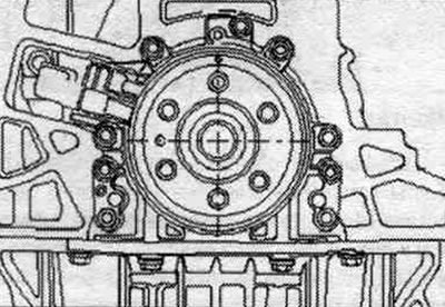
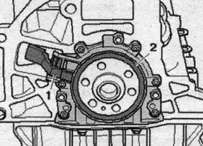
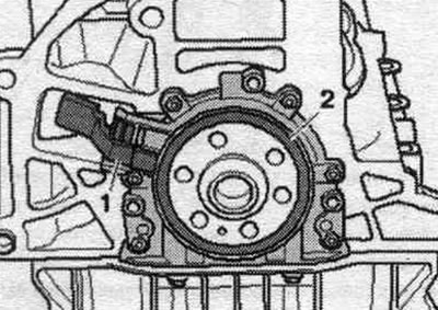
For clarity, all work operations are shown with the engine removed. The operating processes with the engine installed and the gearbox removed are identical. Remove the engine speed sensor "G28" "pos. 1" using a standard spherical attachment.
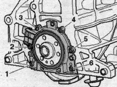
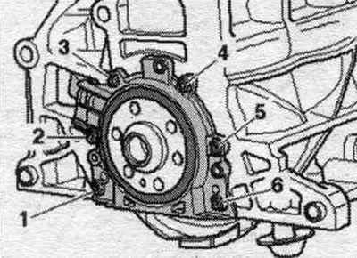
Unscrew bolts "1...6" of the sealing flange.
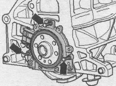
The sealing flange is pressed out from the crankshaft together with the sensor ring. To press out, screw in 3 M6x35 "arrow" bolts one after the other, max. 1/2 turn into the seal. flange. Remove the seal. flange together with the sensor ring.
Pressing in the seal. flange with sensor ring
The sealing flange with a Teflon sealing cuff is equipped with a support ring for the working edges. This support ring serves as a mounting sleeve and must not be removed prior to installation. After removing the seal. flange and sensor ring from the packaging, they must not be separated or twisted. The sensor ring is installed in the mounting position by being fixed on the mounting pin. "T10134" fixture. Sealing flange and seal. the cuff is a single unit and can only be replaced together with the sensor ring. The mounting device "T10134" is brought into the installation position relative to the crankshaft by means of a guide pin, which is inserted into the crankshaft hole.
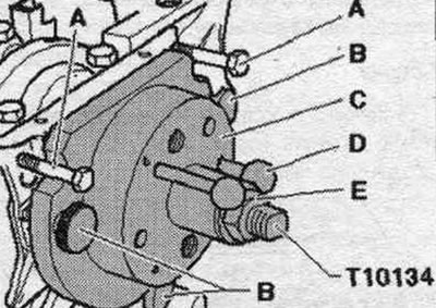
Mounting design. device "T10134"
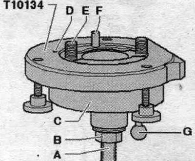
A. Clamping surface; B. Hex nut; C. Mounting cap; D. Locking pin; E. Hexagon socket head cap screw; F. Guide pin for diesel engines (black pen).
A. Installation of seals. flange with sensor ring for mounting. device "T10134"
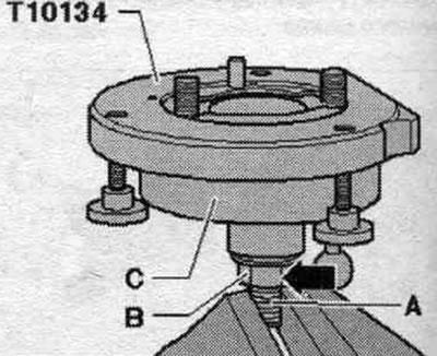
Unscrew the hex nut "B" almost to the clamping surface "A" of the lead screw. Clamp the assembly with a vice. device "T10134" in the area of the clamping surface "A" of the threaded pin. Press on the mount. cap "C" down so that it fits against the hex nut "B". The inner part of the mount. fixtures and installation. the cap must be at the same level.
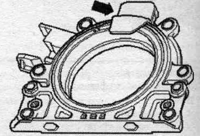
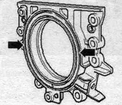
Remove the "arrow" fuse from the new seal. flange. The sensor ring must not be removed from the flange or moved.
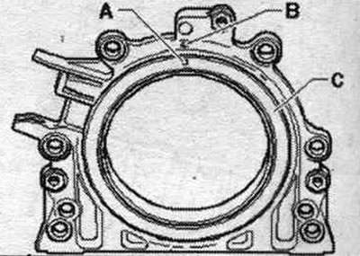
The fixing hole "A" on the sensor ring "C" must be located in line with the mark "B" on the seal. flange. Put the seal. place the flange with the front side on a clean, flat surface.
Press the support ring of the working edges "A" downwards in the direction of the "arrow" until it rests against a flat surface.
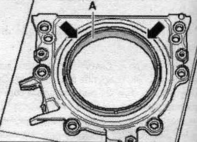
The upper edge of the sensor ring and the front edge are sealed. the flanges must be on the same "arrow" line.
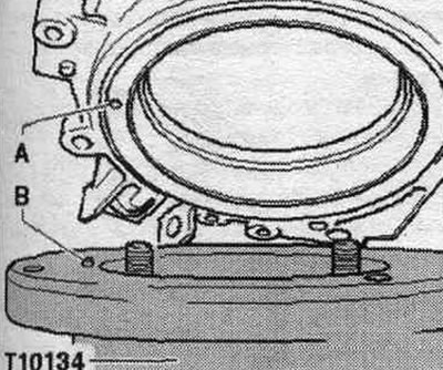
Lay the seal. flange front side on mount. device "T10134" so that the locking pin "B" enters the hole "A" of the timing rotor. Make sure it is compacted. the flange fits snugly against the mounting fixture.
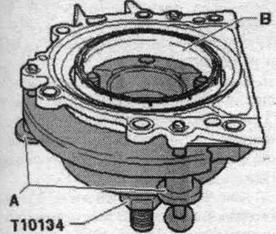
Press on the seal. flange and support ring of the working edges "B" during tightening of three knurled bolts "A" on the mounting surface. "T10134" device to prevent the locking pin from slipping out of the hole in the sensor ring. Make sure that the sensor ring is sealed during installation. the flange remained fixed in the mont. adaptation.
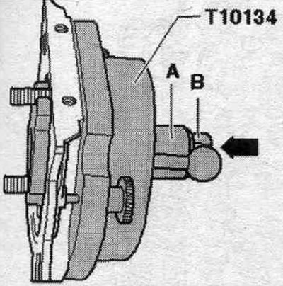
B. Installation of mont. "T10134" fixture with a sealing flange on the crankshaft flange
The crankshaft flange is cleaned of oil and grease. The engine is at TDC. Unscrew the hex nut "B" to the end of the lead screw. Press on the grub screw mont. "T10134" tool in the direction of the "arrow" until nut "B" is flush with mounting cap "A". Align the flat part of the mounting cap. cap in relation to the seating surface of the cylinder block on the oil side. pallet.
Secure the mount. device "T10134" on the crankshaft flange, to do this, screw the bolts into the internal hexagon "A" by approximately 5 thread pitches.
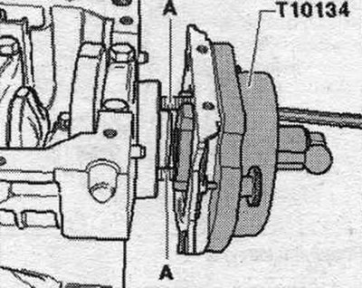
Screw in 2 M7x35 "A" bolts to install the seal. flange into the cylinder block.
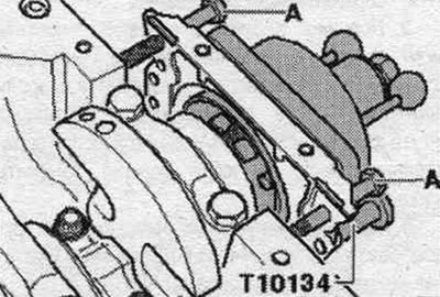
C. Fastening the mont. "T10134" fixture on the crankshaft flange
Move the mounting manually. cap "C" in the direction of the "arrow" so that the support ring of the working edges "B" fits against the crankshaft flange "A". Insert the guide pin for diesel engines (black handle) "F" into the crankshaft hole. This will ensure that the sensor ring takes its final position. position. Hand tighten both Allen head bolts. devices. Thread the hex nut "E" onto the lead screw until it contacts the mounting sleeve "C".
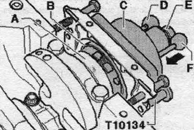
D. Pressing the sensor ring onto the crankshaft flange using the mounting tool. device "T10134"
Tighten the hex nut mounting. "T10134" fixture with a torque of 35 Nm. After tightening the hex nut to 35 Nm between the cylinder block and the seal. there should still be a small gap between the flanges.
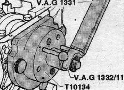
E. Checking the installation. position of the sensor ring on the crankshaft
Unscrew the hex nut "E" until the end of the threaded pin. Remove 2 bolts "A" from the cylinder block. Remove 3 knurled bolts "B" from the seal. flange. Remove the mounting device "T10134". Remove the support ring of the working edges.
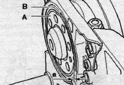
The sensor ring is correctly positioned on the crankshaft if the distance "a" between the crankshaft flange "A" and the sensor ring "B" is 0.5 mm.
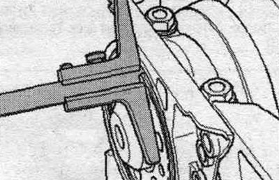
Install the depth gauge on the crankshaft flange. Measure the distance "a" between the crankshaft flange and the sensor ring. If the distance "a" is too small: press the sensor ring further. If the distance "a" corresponds to the specified one: perform the remaining assembly work.
F. Additional pressing of the sensor ring
Secure the mount. device "T10134" "A" on the crankshaft flange, tightening the Allen bolts by hand. Move the mounting manually. "T10134" device for sealing flange.
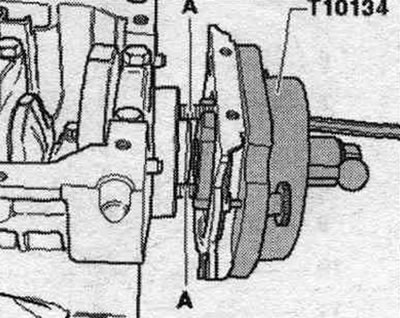
Thread hex nut "E" onto the lead screw until it contacts mounting sleeve "C". Tighten hex nut mount. tighten the T10134 tool to a torque of 40 Nm. Recheck the position of the sensor ring on the crankshaft. If the distance "a" is too small: tighten the hex nut mont. tighten the T10134 tool to a torque of 45 Nm. Recheck the position of the sensor ring on the crankshaft.
Assembly
Installation in reverse order. Tighten the new sealing flange bolts "1...6" in a crosswise pattern.
Screw on the engine speed sensor "G28" "pos. 1". Install the oil pan.
Hang the intermediate shield on the seal. flange and place it on the mounting bushings of the "arrow". Install the driven disk. Install CP.
Pistons and connecting rods
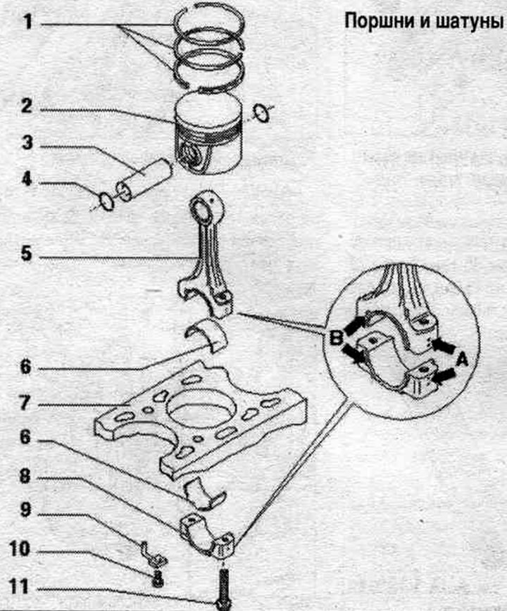
1. Piston rings: place the locks with an offset of 120°; remove and install using piston ring pliers; the "TOP" mark faces the piston bottom.
2. Piston: with combustion chamber; mark mont. position and belonging to the cylinder; the arrow on the piston bottom points towards the belt pulleys; install using a piston ring installer; if scratches appear on the piston skirt, replace the piston.
3. Piston pin: if the pin enters with difficulty, heat the piston to 60°C; remove and install using the "VW 222 A" tool.
4. Retaining ring.
5. Connecting rod: mark the cylinder with a colored pencil "A"; installation position: marks "B" point towards the belt pulleys; the bearing cap is separated by breaking.
6. Bearing insert: install in the proper position; please note: the upper and lower liners are not interchangeable; upper (facing the piston) made of more wear-resistant material; marking: black stripe on the working surface, at the edge of the joint; do not swap used liners; insert bearing shells in the center: check the reliability of the fastening; maximum tolerance of axial displacement: 0.37 mm; measure radial runout using Plastigage measuring strips: maximum tolerance: 0.08 mm, do not rotate the crankshaft when measuring.
7. Cylinder block.
8. Connecting rod cap: install in the proper position; thanks to the connecting rods being constructed using the method of constructive breaking (cracking), the cover can be installed in only one position and only on the corresponding connecting rods.
9. Oil injection nozzle: for piston cooling.
10. Oil injection nozzle bolt: 25 Nm; use without sealant.
11. Connecting rod cap mounting bolt: 30 Nm + 90°; replace; lubricate the threads and mating surface with oil: use old bolts to check the radial runout.
Crankshaft
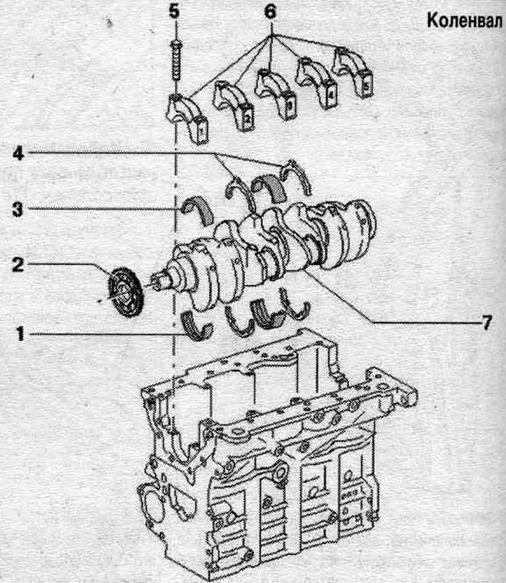
1. Bearing insert: for cylinder block with oil groove; do not interchange previously used bearing shells (mark when removing).
2. Cylindrical gear.
3. Bearing insert: for cover without oil groove; do not interchange previously used bearing shells (mark when removing).
4. Crankshaft axial locking insert: for bearing cap 3; monitor the fixation.
5. Bolt: 65 Nm + 90°; replace; to measure the radial clearance, tighten to a torque of 65 Nm, but do not tighten further.
6. Bearing cover: Bearing cover 1: Belt pulley side, Bearing cover 3 with recesses for adjusting washers; the retaining tabs of the bearing shells on the cylinder block and bearing caps must lie on top of each other.
7. Crankshaft: axial clearance new: 0.17...0.17 mm wear limit: 0.37 mm: radial runout measured using Plastigage measuring strips: 0.03...0.08 mm, tolerance limit: 0.17 mm; when measuring the radial clearance, do not over-tighten the crankshaft.
Removal the timing gear from the crankshaft and installing a new timing gear
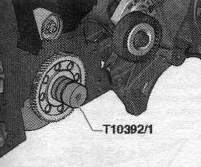
Remove the seal. flange on the belt pulley side. Remove the oil pan. Removing the balance shaft block. The balance shaft module does not need to be replaced, it is sufficient to remove the intermediate gear. Install the "T10392/1" mandrel into the crankshaft console.
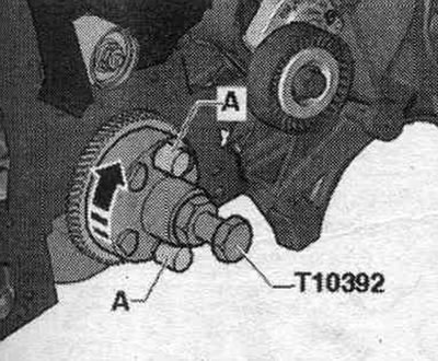
Insert the puller "T10392" into the holes of the gear and turn it clockwise "arrow", screw in the locking pins "A".
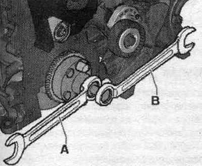
Hold the crankshaft with a ring spanner "A" to prevent it from turning. Remove the spur gear from the crankshaft journal by turning the lead screw with a ring spanner "B".
Installation
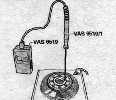
Check the temperature when heating the new toothed gear with the temperature measuring device "VAS 6519". After reaching 200°C, there is approx. 4 seconds. Higher temperatures will increase the installation time (220°C = approx. 6 seconds). Keep the crankshaft end clean. Do not exceed the maximum temperature of 240°C, otherwise the gear will change color or become misaligned. Place the new drive gear face up on a standard hotplate and heat to a temperature between 200°C and 240°C. The inscription should be facing up. Set the temperature measuring device "VAS 6519" to measurement range 2. Install the temperature probe "VAS 6519/1", as shown in the figure, on the flange of the gear, read the temperature readings from the measuring device.
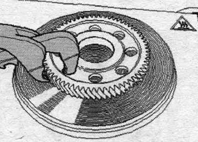
Once the temperature is reached, squeeze the gear with pliers as shown in the figure. In this case, do not allow damage to the teeth of the gear wheel.
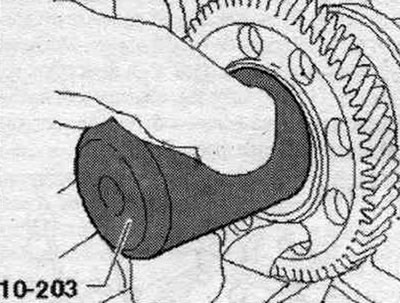
Using the pressing tool "10-203", slowly push the gear wheel by hand without distortion until it stops on the end of the crankshaft. Cool the gear for a few minutes and then install the balance shaft module.