



Table of contents: Installation ↓ Fastening the engine to the manual… ↓ Tightening sequence - clutch module… ↓ Support of units ↓ Removal and installation the engine… ↓ Removal and installation the front… ↓ Support of units ↓
Installation
Tightening torques (Nm)
| Bolts and nuts | M6 | 9 |
| M8 | 20 | |
| M10 | 40 | |
| M12 | 65 |
Fastening the engine to the manual transmission
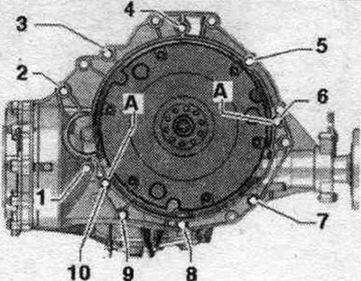
| Pos. | Bolt | Nm |
| 1(3) | M10 x 50 (1) | 65 |
| 2(4) | M12 x 100 (2) | 30 + 90° |
| 3(5), 6 | M12 x 75 (2) | 30 + 90° |
| 4...5(5) | M12 x 120 (2) | 30 + 90° |
| 7...9 | M10 x 75 (2) | 15 + 90° |
| 10 | M12 x 50 (2) | 30 + 90° |
| A | Alignment bushings | |
(1) Steel bolt - do not replace.
(2) Replace the bolts.
(3) Additionally secures the starter.
(4) Additionally secures the starter; equipped with an additional spacer sleeve between the starter and the gearbox.
(5) Additionally secures the cable holder.
Note: Bolts tightened with a tightening angle must be replaced. Replace self-locking nuts, lip seals, gaskets and seals. rings. Hoses and hose fittings syst. air boosters must be cleaned of oils and grease before installation. Secure all hose connections with hose clamps of the appropriate series. To ensure reliable fastening of the boost air hoses to the fittings, all cable ties should be placed in their original locations during installation.
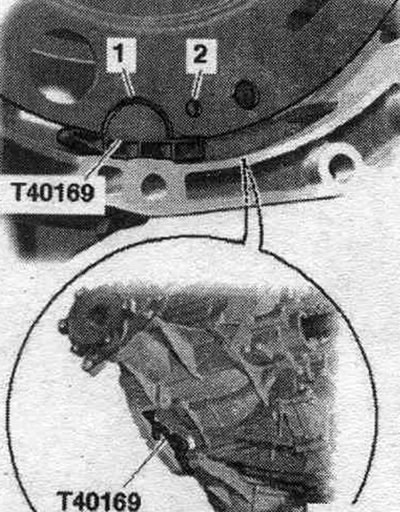
Check the presence of centering bushings in the cylinder block for centering the engine and gearbox; insert any missing centering bushings. Be sure to clean the threaded holes for securing the power unit in the cylinder block with a tap before assembling the transmission. Before connecting the engine and transmission, perform the following preparatory steps. Install the "T40169" auxiliary mounting device from below into the gearbox housing and into the clutch module, as shown in the figure. Auxiliary mont. the "T40169" device should fit into the semicircular cutout "1" and additionally into the inspection hole "2". To locate the inspection hole, it is necessary to rotate the clutch module.
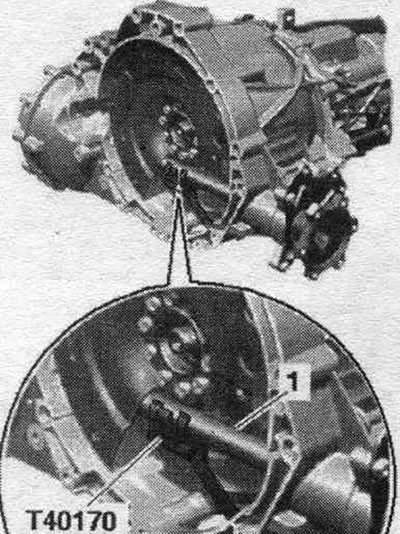
Install the "T40170" holder from below into the gearbox housing and clamp it onto the shaft with flange "1".
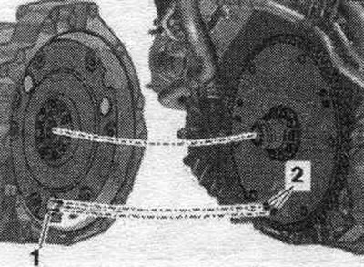
The next step is only necessary if the driven disc with locking pin "2" is installed. Additionally, align the position of the driven disc in relation to the clutch module so that locking pins "2" (if available) on the driven disk could enter the large holes "1" on the clutch module. Problems with clutch performance due to improper installation. If the retaining pins of the driven disk "2" do not enter the holes of the clutch module "1", this can lead to serious problems in the operation of the clutch.
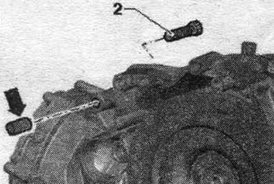
Bolt "2" secures the starter to the gearbox and has an additional. spacer sleeve "arrow." When removing and installing the engine, remember to use the spacer sleeve "arrow." The spacer sleeve should be installed between the starter and the transmission. Insert the starter into the engine mount and secure it to prevent it from falling out.
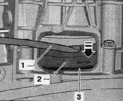
After connecting the engine to the gearbox, it is impossible to install the starter without removing the engine support. Connect the engine and gearbox with flanges, screw in and tighten bolts "2...6". Unload the lead screw of the "10-222 A" crossmember. Lower the service crane and place the engine and gearbox on the engine mounts. Screw in bolts "1" of the engine mounts on the left and right. Remove the service crane and hanging device. Screw in bolt "1" and bolts "7...10" of the engine/gearbox connection and tighten them. "Pos. A" should not be taken into account. Remove bracket "T40170" and installation tool "T40169." This step ensures that the clutch module fits evenly on the driven disc and does not become warped. Lightly press the clutch module "2" using the mounting tool. lever "1" to the driven clutch disc "3" - in the direction of the arrow-.
Tightening sequence - clutch module to driven disc
Tighten the first bolt "arrow" by hand (2 Nm). Turn the crankshaft 120° in the direction of engine rotation and tighten the second bolt by hand. Turn the crankshaft again by 120° in the direction of engine rotation. Now tighten bolt 3 to the specified tightening torque. Now tighten the remaining bolts securing the clutch module to the driven clutch disc. Installation in reverse order. Install the starter. Install a diesel particulate filter. Install the exhaust pipe. Install the counter support and crossbar. Align the system. exhaust gas release without mechanical stress. Take into account cable connections and wiring. Install the engine control unit. Install the wires; splitter 2 cl. 30 "TV22" and cover of the switching unit motor. compartment. Install the stretcher. Install the windshield washer reservoir filler pipe. Pay attention to the battery installation work. Do not use a charger to start the engine! Install the air intake housing. filter. Checking the oil level. Fill with coolant. Install sound insulation and wheel arch liners.
Support of units
Front support and crossmember
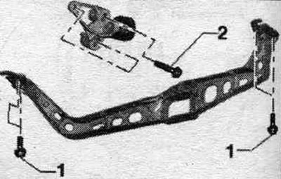
1. 25 Nm; 2. 40 Nm
Removal and installation the engine mount
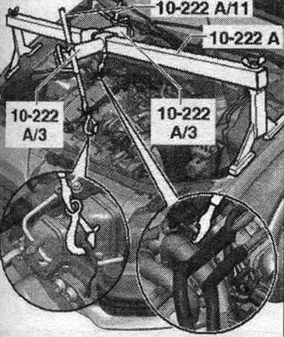
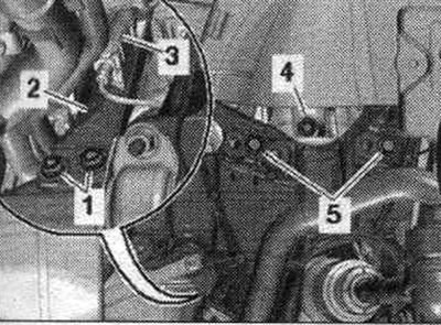
Replace engine mounts only in pairs, left and right. The corresponding mounting shields are also replaced along with them. Remove the engine cover "arrows". Secure the cross beam "10-222 A" with adapters "10-222 A/3" to the body next to the upper shock absorber mounts (right and left), as shown in the picture. Attach the lead screws "10-222 A/11" to the engine suspension eyes. Apply pre-tension using the lead screws. Remove the wheel. Remove sound insulation. Remove the fender liner.
Disconnect and place freely connector "3" on the left solenoid valve for the el. hydr., engine mounts "N144". Unscrew bolts "1, 4, 5" of the engine mount. Set aside the engine mount mounting plate "2". Remove the engine mount.
Install
Installation in reverse order. Bolts tightened at the tightening angle should be replaced. Install sound insulation and wheel arch liners.
Removal and installation the front powertrain support and crossmember
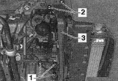
Remove sound insulation. Bring to server. position. Unscrew bolts "1" and remove the front support of the power unit. Unscrew bolts "2" on the left and right, remove crossbar "3".
Install
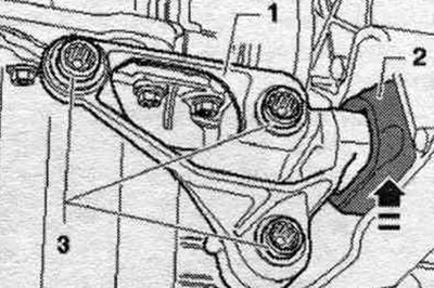
Installation in reverse order. Raise the front engine mount "1" up until it touches the crossmember in the direction of the arrow. The buffer "2" should be flush with the crossmember without any gap or tension. Then tighten bolts "3".
Support of units
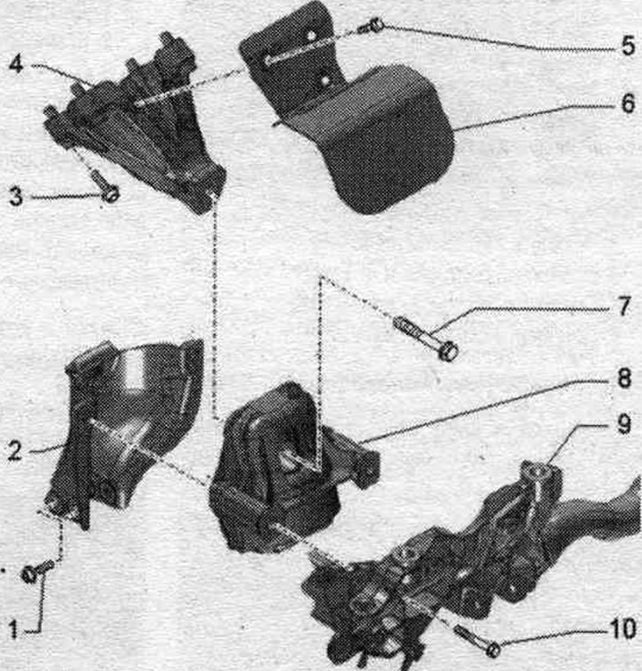
1. Bolt: 20 Nm.
2. Mounting plate: for engine mount; when replacing the engine mount, also replace it.
3. Bolt: 40 Nm.
4. Engine support.
5. Bolt: 10 Nm.
6. Thermal insulation.
7. Bolt: 90 Nm + 90°; replace.
8. Engine mount: left solenoid valve el. hydr., engine mounts "N144"; replace in pairs on the left and right.
9. Subframe.
10. Bolt: 55 Nm.