Table of contents: Toothed belt drive ↓ Installing the fuel injection pump… ↓
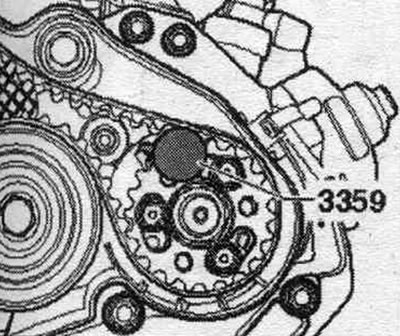
Toothed belt drive
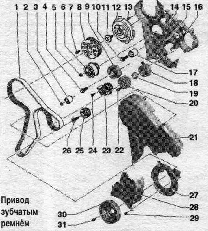
1. Timing belt: Mark the direction of rotation before removing; check the degree of wear; don't overdo it.
2. Nut: 20 Nm.
3. Roller.
4. Bolt; 50 Nm + 90°; replace.
5. Nut: 20 Nm + 45°: replace.
6. Tension roller.
7. Bolt: 20 Nm + 45°; replace.
8. Camshaft drive sprocket.
9. Roller.
10. Bolt: 20 Nm.
11. Bolt: 100 Nm.
12. Hub: Use counter support "3415" to loosen and tighten; to remove, use the "T10052" puller.
13. Bolt: 5 Nm.
14. Rear timing belt cover.
15. Bolt: 20 Nm.
16. Bolt: 5 Nm.
17. Roller.
18. Hub: with sensor crown; for unscrewing and tightening, use the counter support "T10051"; to remove, use the "T40064" puller.
19. Nut: 100 Nm.
20. High pressure pump toothed belt pulley.
21. Upper part of the toothed belt protective cover.
22. Bolt.
23. Coolant pump.
24. Bolt: 15 Nm.
25. Crankshaft toothed pulley.
26. Bolt: 120 Nm + 90°; replace: use counter support "3415" for loosening and tightening; thread and flange add. do not lubricate; tightening can be done in several steps.
27. Lower part of the toothed belt protective cover.
28. Middle part of the toothed belt protective cover.
29. Bolt: 10 Nm.
30. Belt pulley/torsional vibration damper: installation is only possible in one position (the holes are located with an offset).
31. Bolt: 10 Nm + 90°; replace.
Take off
Adjustment of the timing belt is performed only on a cold engine, since the adjustment position of the tensioner changes depending on the temperature. Remove the vibration damper. Release the arrow clamps and remove the timing belt protective cover.
Turn the tensioner in the direction of the arrow, remove the poly V-belt from the generator pulley and relieve tension on the tensioner. Remove the poly V-belt.
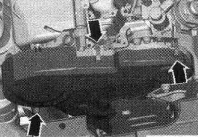
Remove the middle and lower timing belt covers "arrows".
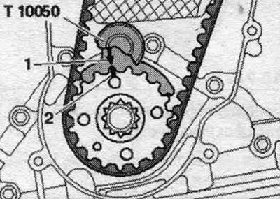
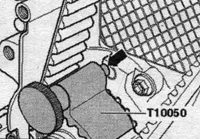
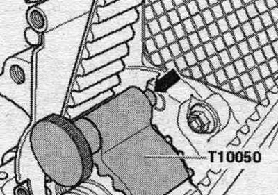
Rotate the engine to TDC and hold the timing belt sprocket on the crankshaft using the T10050 crankshaft stopper. To do this, slide the crankshaft stopper from the end face of the timing belt sprocket onto the toothed mesh. The camshaft timing gear should be positioned at 12 o'clock. The marks on the crankshaft timing gear pulley "2" and the crankshaft locking tool "T10050" "1" should align. In this case, the journal of the crankshaft locking tool "T10050" must enter the hole in the flange.
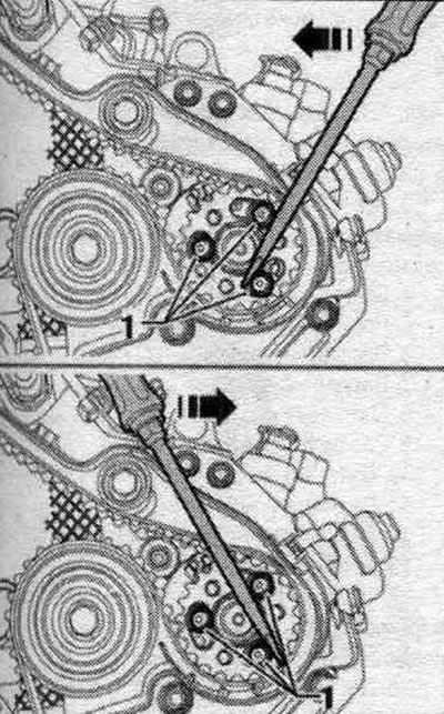
Mark the direction of rotation of the timing belt. Loosen bolts "1" of the camshaft pulley.
Loosen bolts "1" of the toothed belt sprocket on the high pressure pump.
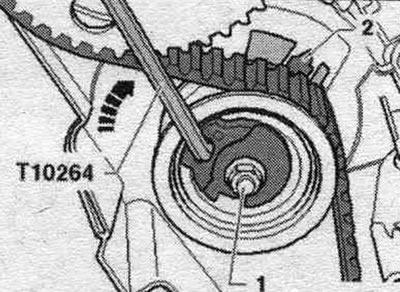
Loosen the tension roller fastening nut "1". Turn the tension roller eccentric counterclockwise using the socket wrench "T10264" "arrow" so that the tension roller can be fixed with the locking pin "T10265".
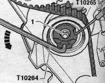
Then turn the tension roller eccentric clockwise "arrow" until it stops and tighten the fastening nut "1" by hand.
Remove the toothed belt first from the idler pulley, then from the remaining pulleys.
Installation
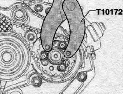
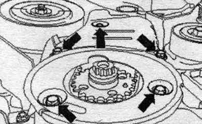
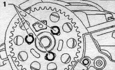
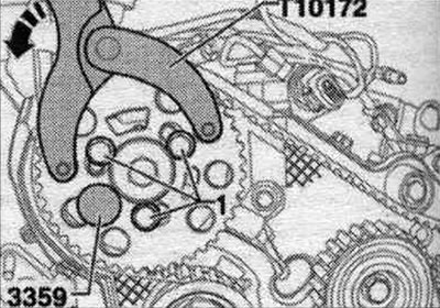
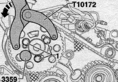
Installation in reverse order. The tension roller must be secured using the "T10265" clamp on the right stop. The crankshaft is secured using the T10050 crankshaft stop. If necessary, rotate the camshaft hub using the T10172 stop and T10172/4 adapter to a position where it can be secured. To do this, at least tighten bolt "1" by hand. Secure the camshaft hub with locking pin "3359." To do this, insert the locking pin into the hole in the cylinder head through the free groove in the camshaft pulley.
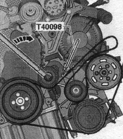
If necessary, use a screwdriver to turn the fuel injection pump hub to a position where it can be locked (the screwdriver should be rested on the bolt heads as shown in the figure).
Installing the fuel injection pump hub in the proper position
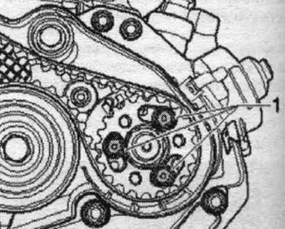
Secure the high-pressure pump hub using locking pin "3359." To do this, insert the pin into the groove on the outside of the timing belt sprocket.
Turn the camshaft pulley and the fuel injection pump pulley in the concentric grooves in a clockwise direction until they stop. Place the timing belt on the crankshaft gear, tension roller, camshaft gear, coolant pump gear and high pressure pump gear. Place the timing belt last on the idler pulley. Loosen the nut securing the tensioner roller and remove the retainer "T10265". Pay attention to the correct seating of the tensioner roller in the rear part of the toothed belt cover "arrow".
Install the counter support "T10172" as shown in the figure. Press the counter support "T10172" in the direction indicated by the arrow and keep the camshaft pulley under pre-tension. Tighten bolts "1" of the camshaft gear and the high-pressure pump gear in this position to a torque of 20 Nm.
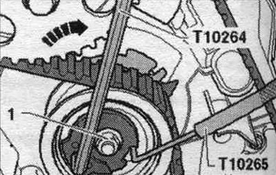
Rotate the tension roller eccentric clockwise using the T10264 angle screwdriver until the pointer "2" is in the center of the hole in the support plate. Make sure that the fastening nut "1" does not rotate.
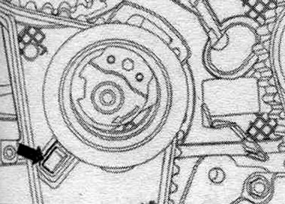
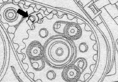
Lock the tension roller in this position and tighten the tension roller fastening nut as described below to a torque of 20 Nm and turn it further by 45°. Remove the locking pins "3359" and the crankshaft stop "T10050". Turn the crankshaft min. 2 turns in the direction of engine rotation and install it, slightly short of TDC of the 1st cylinder. Reinstall the crankshaft stopper "T10050" on the toothed belt gear on the crankshaft. Rotate the crankshaft in the direction of engine rotation until the crankshaft stop pin "arrow" stops rotating and engages with the seal. flange.
Further testing involves simultaneously installing the camshaft and crankshaft locks. Re-fixing the fuel injection pump hub is unlikely to be possible. However, a slight deviation of the "arrow" will not affect the engine's operation.
Check whether the camshaft hub can be secured using the "3359" locking tool; is the roller pointer in the range between the center of the hole in the base and a location 5 mm to the right of the hole in the base?.
If you cannot fix the camshaft hub
Pull the crankshaft locking tool "T10050" slightly towards you so that its pin comes out of the hole in the cover. Turn the crankshaft counterclockwise slightly past TDC. Then slowly turn the crankshaft in the engine's direction of rotation until the camshaft hub can be locked. After fixing, loosen the camshaft timing pulley screws.
If the crankshaft locking pin "T10050" is on the left near the hole
Now rotate the crankshaft in the direction of engine rotation until the stop pin stops rotating and engages with the seal. flange. Tighten the timing belt sprocket bolts on the camshaft to a torque of 20 Nm.
If the crankshaft locking pin "T10050" is on the right near the hole
Turn the crankshaft again against the direction of engine rotation. Now rotate the crankshaft in the direction of engine rotation until the stop pin stops rotating and engages with the seal. flange. Tighten the timing belt sprocket bolts on the camshaft to a torque of 20 Nm.
Continuation
Remove locking pin "3359" and crankshaft stop "T10050". Turn the crankshaft min. 2 turns in the direction of engine rotation and install it, slightly short of TDC of the 1st cylinder. Repeat the check. If it is possible to secure the camshaft hub, tighten the bolts as follows. Camshaft gear: turn an additional 45°. Hold with counter support "T10172" and adapters "T10172/4". High-pressure pump gear: turn an additional 90°. Hold with counter support "T10172" and adapters "T10172/7".