
Table of contents: Valve mechanism ↓ Removal and installation camshafts ↓ Replacing valve stem seals with the… ↓
Valve mechanism
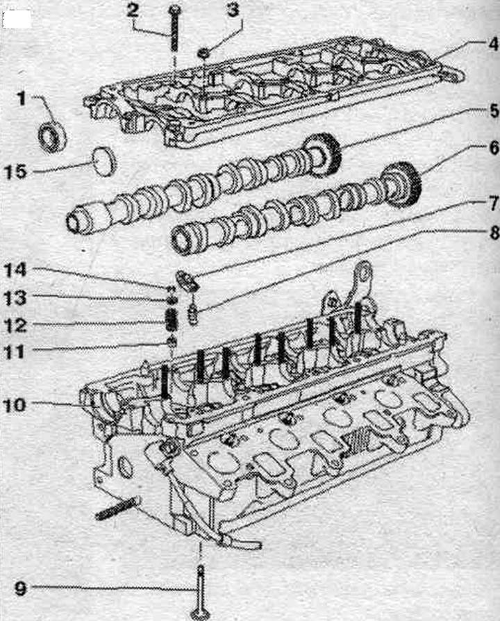
1. Lip seal: the working edge of the lip seal add. do not lubricate; before installation, remove any remaining oil from the camshaft journal with a clean cloth; to install, seal the groove on the camshaft cone (for example, Tesafilm film).
2. Bolt: observe the sequence when unscrewing, observe the sequence when tightening.
3. Nut: 10 Nm.
4. Camshaft frame: with built-in camshaft liners, observe the sequence when loosening, observe the sequence when tightening; clean the sealing surface; modification of the sealing surface is not permitted.
5. Exhaust camshaft.
6. Intake camshaft.
7. Rocker arm: mark the location, do not change places: check the roller bearing for ease of movement; grease the work surface with oil.
8. Hydraulic compensator: mark the location; before installation, lubricate the working surfaces.
9. Valve: cannot be machined, only lapping is allowed; mark mont. reinstallation position.
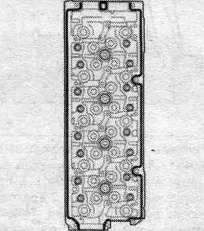
10. Cylinder head: follow instructions.
11. Valve stem seal: Replace the valve stem seals.
12. Valve spring.
13. Valve spring plate.
14. Valve cracker.
15. Cover: replace.
Disconnecting the crankshaft frame
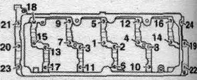
Loosen the crankshaft frame mounting bolts in sequence. "24...1".
Frame - sequence, tightening
Tighten the cylinder head bolts in sequence. "1...24" as follows.
1. Tighten the bolts by hand in several stages in sequence. "1...24".
2. Tighten the bolts in sequence. "1...24" torque wrench with a torque of 10 Nm.
Removal and installation camshafts
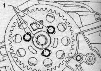
Remove the "arrow" engine cover. Remove the injector noise-insulating cover. Remove the injectors. Remove the fuel rail. Remove the camshaft and high-pressure pump timing belt. Remove the cylinder head cover. Unscrew bolts "1" of the camshaft drive gear. Remove the camshaft from the hub.
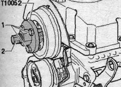
Hold the hub with the T10051 counterstop and loosen hub mounting bolt "1." Loosen the hub mounting bolt approximately 2 turns.
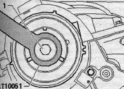
Install the "T10052" puller and align it with the hub holes. Tighten the mounting bolts "1". Increase the tension of the hub by uniformly tightening the puller "2" until the hub is disconnected from the camshaft cone. In this case, fix the puller using a 30 wrench.
Remove the hub from the camshaft cone. Remove the vacuum pump. Remove vacuum hose "1".
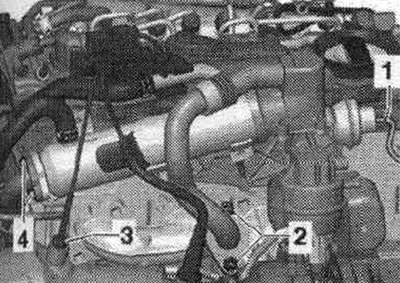
Unscrew bolts "2" and "4". Do not unscrew lines "1" and "2". Unscrew the "arrow" bolts and tie up the system cooler. exhaust gas recirculation.
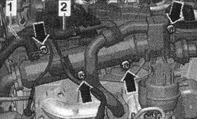
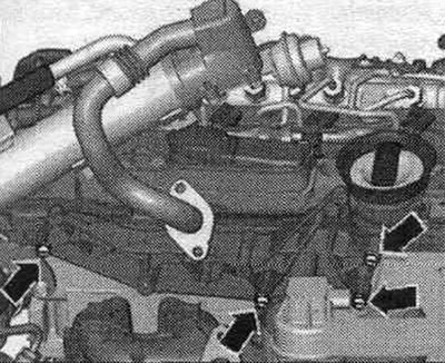
Unscrew the arrow bolts and remove the EGR system bracket.
Loosen the frame mounting bolts in sequence. "24...1". Remove the camshaft frame. Mark for reinstallation and remove the camshafts.
Installation
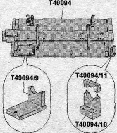
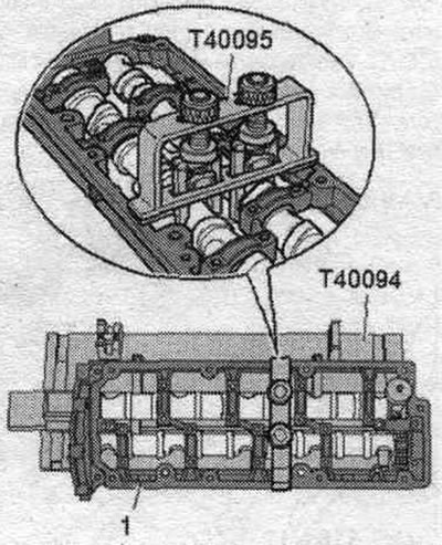
Apply silicone sealant to the mating surfaces between the crankshaft frame and cylinder head. This can damage the thrust bearing in the crankshaft frame. Camshafts should only be installed using the T40094 camshaft stand as described below. Using an electric drill with a plastic bristle attachment, remove any remaining sealant from the mating surfaces of the cylinder head and crankshaft frame. Remove any remaining sealant from the cylinder head and crankshaft frame, for example, using a rotating brush attachment with plastic bristles. Clean the sealing surfaces from oil and grease. Lubricate the working surface of the camshafts with oil. Equip the camshaft installation tool "T40094" as follows: screw the supports "T40094/9" and "T40094/10" (using "T40094/11") to the main plate, as shown in the figure. If necessary, remove the supports fixed in this place.
Install support "T40094/1" to position "F" and support "T40094/2" to position "A".
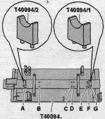
Place the intake camshaft on the supports "T40094/1" and "T40094/2". Turn the intake camshaft so that it can be locked with the retainer in the "TDC" position "arrow 1". The concavity "arrow 2" of the cylinder head bolt must face outwards.
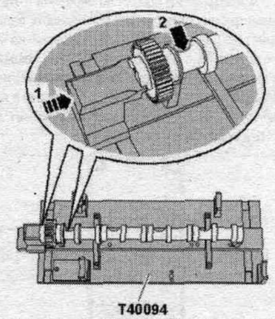
Place the exhaust camshaft on supports "T40094/9" and "T40094/11". Secure the exhaust camshaft with cover "T40094/11". Protrusion "1" of the cover must fit into groove "2" in the camshaft. Install the clamping tool "T40096/1" on the gear engagement of the exhaust camshaft so that each neck of the clamping tool engages on each half of the gear. The wide neck should fit into the wide half of the gear. Tighten the clamping device with the knurled wheel until the tooth profiles are level. Move the intake camshaft towards the exhaust camshaft so that their teeth engage in the "arrow" pattern.
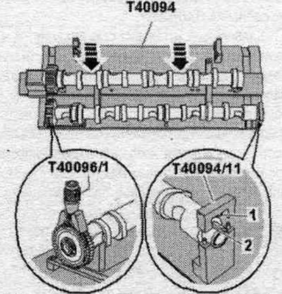
Install the frame onto the camshafts. All camshaft bearings must be located on the camshafts. Install the camshaft frame "T40095" and secure the camshafts in the frame as shown in the figure. Remove cover "T40094/11".
Cut off the tip of the tube along the front mark (hole diameter is about 2 mm). Apply beads of sealant (approx. 2...3 mm) "arrows" onto the clean seating surfaces of the cylinder head, as shown in the figure. The sealant beads should not be thicker than specified, otherwise excess sealant may get into the camshaft bearings.
Remove the camshafts together with the frame, the "T40095" camshaft stand, and the "T40096/1" clamping tool from the "T40094" camshaft stand and carefully insert them into the cylinder head. Tighten the frame mounting bolts in sequence. "1...24" at first by hand. The frame must fit snugly against the cylinder head over the entire mating surface. Tighten the frame bolts in sequence. "1...24". Remove the camshaft installation tool "T40095" and the clamping device "T40096/1".
Further installation is carried out in reverse order, taking into account the following. Replace camshaft seals. Press the new sealing cover onto the cylinder head using a suitable mandrel until it is flush. Install a vacuum pump. Install the cylinder head cover. Risk of damage to valves and piston crowns after working on the valve train. Since the hydraulic lifters must be settled, after installing the camshafts the engine should not be run for approx. 30 min. To ensure that no valves come into contact with the cylinder head during operation, carefully rotate the crankshaft at least 2 revolutions.
Replacing valve stem seals with the cylinder head installed
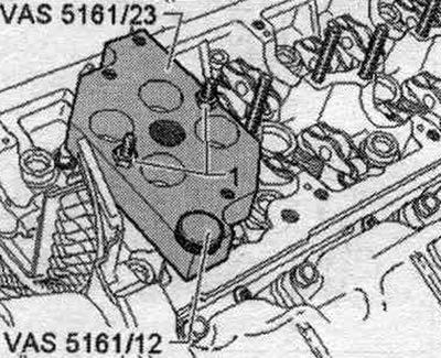
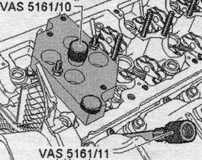
Remove the glow plugs with a 3220 wrench. Remove the camshafts. Install the guide plate "VAS 5161/23" onto the cylinder head. Secure the guide plate "VAS 5161/23" from the intake manifold side with a knurled bolt "VAS 5161/12" and secure it to the studs with M6 "1" nuts without flanges, tightening them by hand. Sealing bolt "VAS 5161/10" screw into the guide plate "VAS5161/23".
Screw in the adapter "VAS 5161/11" into the threaded hole for the glow plug.
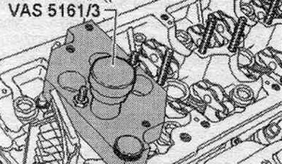
Install a beard "VAS 5161/3" into the guide plate "VAS 5161/23" and knock out the tightly seated valve crackers with a plastic hammer.
Toothed element "VAS 5161/5" with a fork "VAS 5161/6" screw into the guide plate "VAS 5161/23". Fit the knurled spacer ring "VAS 5161/23-1" on the mounting cartridge "VAS 5161/8".
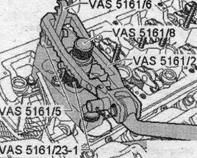
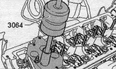
Connect the adapter through a regular adapter "VAS 5161/11" to the compressed air line and apply constant pressure. Minimum pressure: 6 bar overpressure. Hang the push fork "VAS 5161/2" to the grille and press the mounting. cartridge "VAS 5161/8" down. At the same time, turn the knurled bolt mount. cartridge to the right until the ends enter the valve crackers. Turn the knurled screw slightly back and forth, this will cause the valve pins to expand and be captured by the mounting chuck "VAS 5161/8". Release the push fork. Extract mont. cartridge "VAS 5161/8" with a spacer ring, a valve plate and a valve spring. Remove the valve stem seals using the puller "3364".
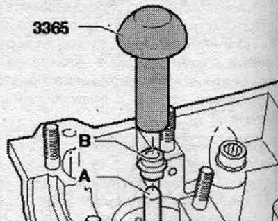
The new valve stem seals come with a plastic bushing "A." Install the plastic bushing "A" onto the valve stem to prevent damage to the new valve stem seals "B." Lightly lubricate the sealing lip of the valve stem with oil. Install the oil seal onto the plastic sleeve. Carefully press the valve stem seals into the valve guide using the "3365" valve stem seal press tool. Remove the plastic sleeve "A".
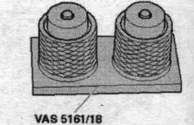
Insert the valve spring and valve retainer into the cylinder head. If the valve keepers were removed from the installation. cartridge "VAS 5161/8", then first they need to be inserted into the mount. device "VAS 5161/18". The larger diameter of the valve cracker faces upward. Mount the mount. cartridge "VAS 5161/8" on top of the mont. device and grab the valve crackers.
Reinsert the mont. cartridge "VAS 5161/8" into the guide plate. Press the mount. cartridge "VAS 5161/8" using a push fork "VAS 5161/2" down. Turn the knurled bolt onto the mounting. cartridge in one direction and the other, while pulling it upward. When unscrewing the knurled bolt, release the push fork "VAS 5161/2". Installation in reverse order. Install glow plugs. Install the camshafts. After installing the camshafts, the engine must not be started for approximately 30 minutes. The hydraulic lifters must be settled (otherwise the valves will touch the pistons). After working on the valve mechanism, crank the engine by hand for at least 2 revolutions to ensure that no valve is in contact with the piston.