
Overview of installation locations
Nodes A to J are not shown in the drawing.
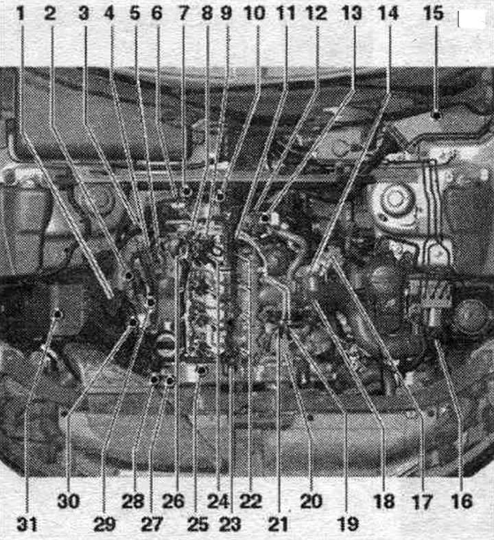
1. Air flow meter "G70".
2. Lambda probe "G39" with lambda probe heating element "Z19".
3. Exhaust gas temperature sensor 3 "G495".
4. Electrical connector of exhaust gas temperature sensor 3 "G495".
5. Plug connector of the lambda probe "G39".
6. Exhaust gas pressure sensor 1 "G450": after replacement, adjustment must be made.
7. Radiator outlet coolant temperature sensor "G83".
8. Fuel temperature sensor "G81".
9. Pressure reducing valve: the task of the pressure reducing valve is to maintain residual pressure in the return fuel. the line pressure is always around 10 bar, this is necessary for the injectors to operate normally; the pressure reducing valve should only be replaced as a set with the return fuel lines; after replacement, it is necessary to let the engine idle for about 2 minutes to remove air from the fuel. highways.
10. Coolant temperature sensor "G62".
11. Fuel pressure regulating valve "N276": 80 Nm.
12. Variable geometry intake manifold servomotor "V183": with variable geometry intake manifold position sensor "G513".
13. Engine speed sensor "G28": 4.5 Nm.
14. Intake manifold flap motor "V157": with throttle valve potentiometer "G69".
15. Engine control unit "J623".
16. Boost pressure sensor "G31": common element with intake air temperature sensor "G42".
17. Radiator pump system. exhaust gas recirculation "V400".
18. EGR valve "N18" with system potentiometer. exhaust gas recirculation "G212".
19. Connecting the return fuel. highways.
20. High-pressure pump with fuel metering valve "N290"; do not open the fuel metering valve "N290".
21. Fuel connection. highways.
22. Glow plugs: Glow plug 1 "Q10". Glow plug 2 -Q11 -. Glow plug 3 "Q12". Glow plug 4 "Q13".
23. Fuel pressure sensor "G247": 100 Nm.
24. Injectors.
25. Hall sensor "G40".
26. Return fuel. highways: return fuel. do not disassemble the lines - they can only be replaced together with the pressure reducing valve; after replacement, let the engine idle for two minutes to remove air from the fuel. system, then check the return fuel lines for leaks. highways.
27. Electromagnetic boost pressure limiting valve "N75".
28. Radiator changeover valve system. exhaust gas recirculation "N345".
29. Electrical connector of exhaust gas temperature sensor 1 "G235".
30. Boost pressure regulator position sensor "G581".
31. Air bypass valve. filter "N275": units (bypass damper with air bypass damper valve. filter "N275") are not installed in all equipment variants and not for all countries.
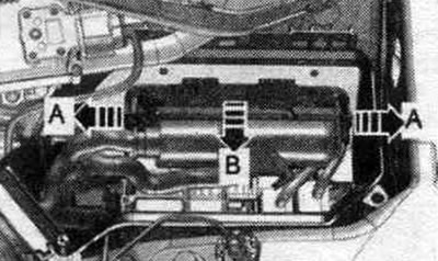
A. Relay and fuse block in the switchboard. block in the left water drainage box.
B. Low-power heating relay "J359" and high-power heating relay "J380".
C. Brake light sensor "F" and foot brake pedal position sensor "F47": in the footwell on the gas pedal.
D. Clutch pedal position sensor "G476": installed only on vehicles with manual transmission.
E. Accelerator pedal position sensor "G79" and accelerator pedal position sensor 2 "G185".
F. Additional fuel. pump "V393".
G. Exhaust gas temperature sensor 1 "G235": 45 Nm.
H. Exhaust gas temperature sensor 4 "G648": 45 Nm.
I. Electrical connector of exhaust gas temperature sensor 4 "G648".
J. Diesel particulate filter: mounted on the bottom; common element with the catalyst; after replacement, adjustments must be made.
After replacing the exhaust gas pressure sensor 1 "G450" and/or the dust filter, it is necessary to carry out adaptation. The procedure is described in the Guided Functions; the Tester should be used for this.
Installation location of the engine control unit "J623"
On the left there is a switch. engine compartment block.
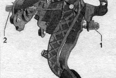
Accelerator pedal position sensor "G79" and accelerator pedal position sensor 2 "G185"
The accelerator pedal position sensor "G79" and the accelerator pedal position sensor 2 "G185" are integrated into the accelerator pedal module and cannot be replaced separately.
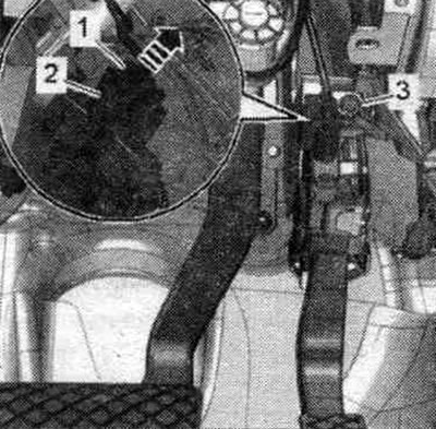
Brake light switch "F" and brake pedal position sensor "F47" "1"
2. Clutch pedal position sensor "G476".
Built-in components: Clutch pedal switch for engine starting "F194" and clutch pedal switch "F36" (only for manual transmission).
Installation locations
1. Fuel pressure sensor "G247". 2. Fuel pressure regulating valve "N276". 3. Variable geometry intake manifold servomotor "V183" with variable geometry intake manifold position sensor "G513". 4. Variable geometry intake manifold servomotor "V157" with throttle valve potentiometer "G69". 5. EGR valve "N18" with syst. potentiometer. eGR valve "G212". 6. Fuel metering valve "N290".
Radiator pump system. exhaust gas recirculation "V400"
Hall sensor "G40"
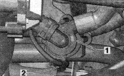
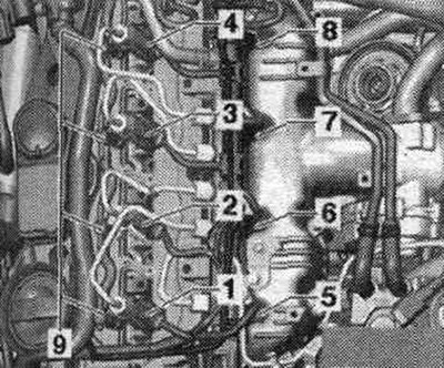
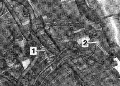
Rear engine components
1. Exhaust gas pressure sensor 1 "G450". 2. Radiator outlet coolant temperature sensor "G83".
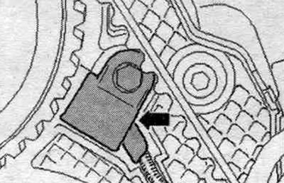
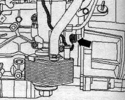
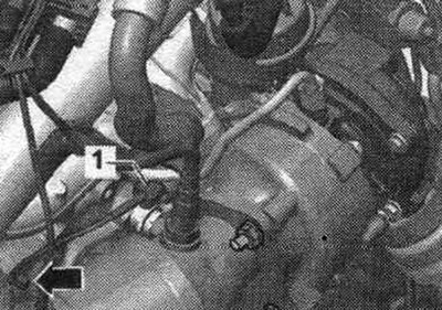
Engine speed sensor "G28" "arrow"
Additional fuel. pump "V393" "3"
1. Additional plug connector. fuel pump "V393". 2. Fuel filter. 4. Heating valve.
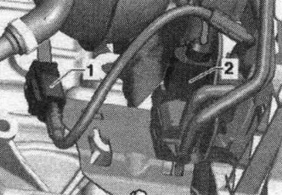
Details
1. Fuel pressure regulating valve "N276". 2. Servomotor of the intake manifold with variable geometry "V183".
Boost pressure sensor "G31" with intake air temperature sensor "G42" "arrow"
Common structural element.
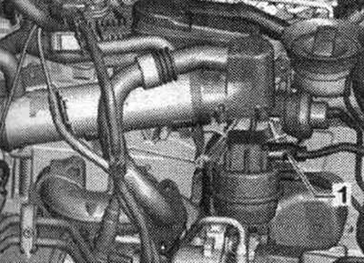
Boost pressure regulator position sensor "G581" "1"
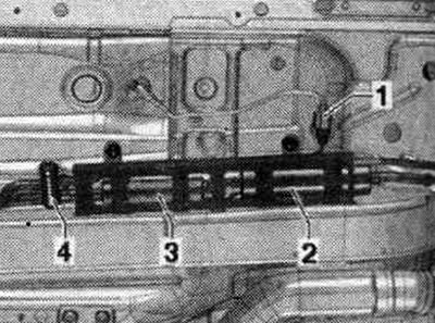
Injectors and glow plugs
1. Injector cyl. 1 "N30". 2. Cyl. injector. 2 "N31". 3. Cyl. injector. 3 "N32". 4. Cyl. injector. 4 "N33". 5. Glow plug 1 "Q10". 6. Glow plug 2 "Q11". 7. Glow plug 3 "Q12". 8. Glow plug 4 "Q13". 9. Return fuel fittings. highways.
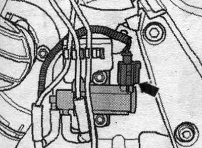
Electromagnetic pressure limiting valve "N75" "arrow"
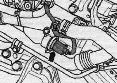
Coolant temperature sensor "G62" "arrow"
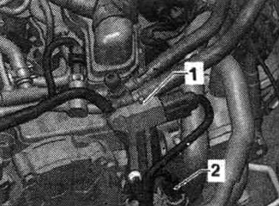
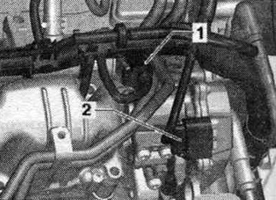
Details
1. Plug connector of the exhaust gas temperature sensor 1 "G235". 2. Radiator changeover valve syst. exhaust gas recirculation "N345".
Exhaust gas temperature sensor 1 "G235" "1"
Details
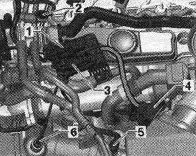
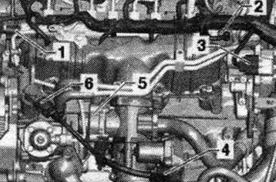
1. Electrical connector of lambda probe "G39" with lambda probe heater "Z19". 2. Fuel temperature sensor "G81". 3. Electrical connector of exhaust gas temperature sensors 3 "G495". 4. Air flow meter "G70". 5. Lambda probe "G39" with lambda probe heating element "Z19". 6. Exhaust gas temperature sensor 3 "G495".
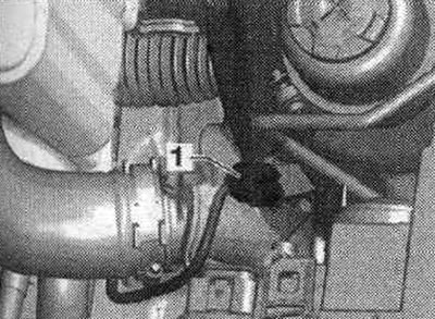
Exhaust gas temperature sensor 4 "G648" "2"
1. Plug connector of exhaust gas temperature sensor 4 "G648".