
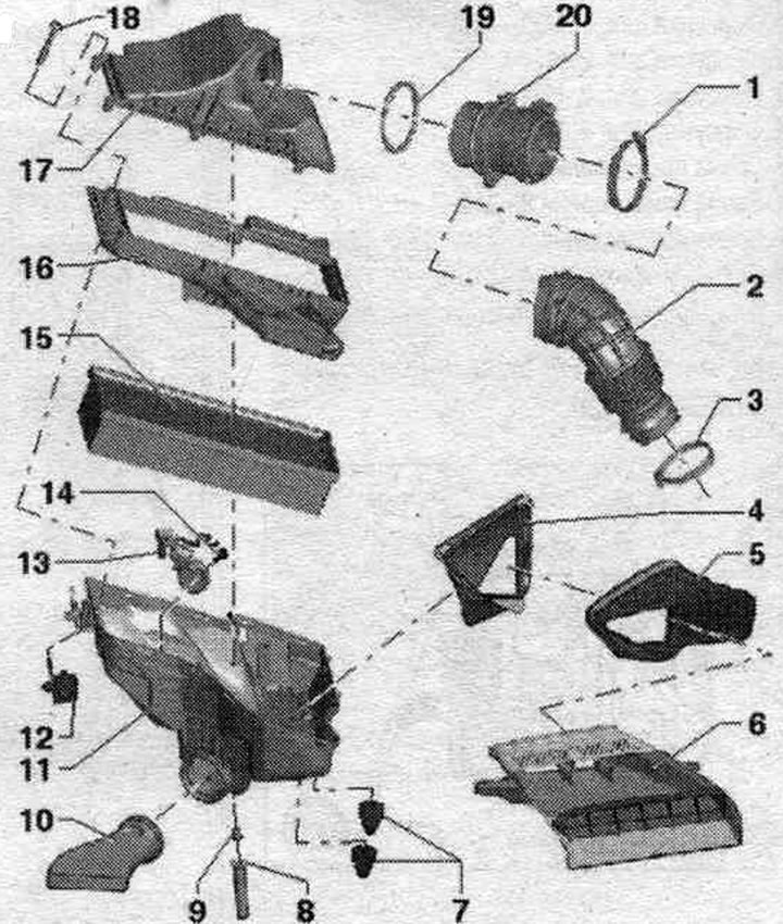
1. Hose clamp: 3.5 Nm.
2. Air duct hose.
3. Hose clamp: 3.5 Nm.
4. Air duct: fixed in the air duct housing. filter; clean the air duct from dirt and leaves.
5. Air duct: clean the air duct from dirt and leaves.
6. Air duct: tighten to the lock frame with a torque of 2 Nm; clean the air duct from dirt and leaves.
7. Rubber tip.
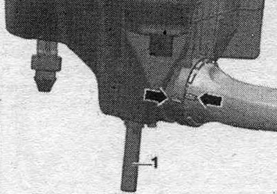
8. Water drain hose: Clean the water drain hose from dirt and leaves (important).
9. Water drainage hose guide.
10. Heated air supply line (only in countries with cold climates): Insert the heated air supply line into the air filter until it stops and turn it clockwise until it clicks.
11. Lower part of the air. filter: Clean the lower part of the air filter. filters from salt deposits, dirt and leaves; check the drain for contamination and clean if necessary (important).
12. Fastening for the lower part of the air. filter: fix (with a clear feeling); do not use lubricants.
13. Air bypass valve. filter "N275": with intake air switching flap.
14. Bolt: for air bypass valve. filter "N275".
15. Replaceable air element. filter: always use the original filter element: also clean the fine filter (if installed).
16. Nozzle for the lower part of the air. filter.
17. Upper part of the air. filters: Clean the top of the air filter. filters from salt deposits, dirt and leaves.
18. Bolt.
19. Sealing ring: replace if damaged.
20. Air flow meter.
Removal and installation the air liner. filter
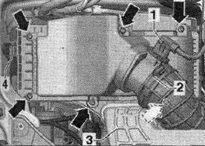
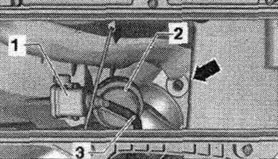
Disconnect the electrical. plug connector "1" from the air flow meter "G70". Open clamp "2" of the air duct going to the turbocharger and remove the hose from the air flow meter "G70". Unscrew all the "arrow" bolts from the top of the air flow meter. filter and remove it in an upward direction. Remove the old air filter element. filter.
Install
To ensure the G70 air flow meter functions properly, it is essential to follow these instructions and steps. If the replaceable air element is heavily soiled or saturated with moisture. filters, dirt particles or moisture can get into the G70 air flow meter and distort the data obtained. This will result in a loss of power as less fuel injection volume is calculated. Use only the original filter element. Hoses and hose fittings syst. air boosters must be cleaned of oils and grease before installation. Do not use silicone-containing lubricants during installation. The air filter housing must be clean. To secure all hose connections, use clamps of the appropriate series. When cleaning the filter housing with compressed air: to prevent damage, cover sensitive components such as the flow meter, air intake, etc. with a clean rag. Blow out the "arrow" drain at the bottom of the air intake with compressed air. filter.
Clean the air duct housing. filter (upper and lower parts) from residual salts, dirt or leaves (if necessary, clean by pumping out). Check the air flow meter and air duct hose (side of clean air) for the presence of salt residues, dirt and leaves. Check the air duct from the closing panel to the air duct housing. filters to ensure they are free of dirt and leaves. When installing the filter element, make sure that it is centered in the lower part of the air duct. filter. Carefully, without applying much force, install the upper part of the air filter. filters to the bottom. At the same time, make sure that the upper part of the air. the filter was not installed crookedly (monitor the working edge of the filter insert seal). Check the air supply hose's tightness on the G70 mass air flow sensor. Install in reverse order.
Removal the lower part of the air. filter
Disconnect the electrical. connector "1" from the air flow meter "G70." Open clamp "2" of the air duct leading to the turbocharger and remove the hose from the air flow meter "G70." Remove air duct "3." Remove the vacuum line "arrow." (if available).
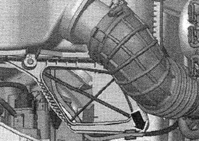
Unlock the "4" fastening of the lower part of the air. filter (press the rubber parts on the right and left and remove them upwards). The parts (bypass valve with air inlet changeover valve "N335" "1") are not installed in all trim levels and not for all countries. When installing the fastener, do not use lubricants. Disconnect the connector of the air intake switching valve "N335" (if available). Carefully remove the air duct housing. filter.
Install
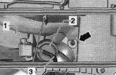
To ensure the G70 air flow meter functions properly, it is essential to complete the following steps. If a warm air intake pipe is installed (only in the version for countries with cold climates), ensure that the suction pipe "arrow" is correctly fixed (follow the markings). Check the condensate drain hose "1" at the bottom of the air conditioner. filters for dirt and clots (clean if necessary).
Clean the air duct housing. filter (upper and lower parts) from residual salts, dirt or leaves (if necessary, clean by pumping out). Check the air flow meter and air duct hose (side of clean air) for the presence of salt residues, dirt and leaves. Check the intake duct before the air intake element is replaced. filters for dirt. Connect the connector to the air bypass valve. filter "N275" (if available). Install the lower part of the air. filter. The water drain hose should be laid straight down and not be kinked. Attach vacuum hose "3" (if available) to connect the air bypass damper valve. filter "N275" "1". Carefully, without applying much force, install the upper part of the air. filters to the bottom. Before tightening the bolts, check again that the upper part is located in the groove of the lower part of the air. filter (air leakage through leaks).
Screw the top part of the air. filter to the bottom. Ensure the G70 air flow meter air duct hose is tightly seated. Reconnect the G70 air flow meter plug. Reinstall in reverse order.
[The original version is on the portal «AudiManual.ru»]