Repair Chevrolet Repair Toyota Repair Honda Repair AvtoVAZ Repair Mercedes-Benz Repair BMW Repair Opel
Home  |  Contacts  |  Sitemap  |    
English Русский
Български
Беларускі
Український
Српски
Hrvatski
Română
Polski
Slovenský
Magyar
AudiManual.ru


  • AUDI 80
  • AUDI 100
  • AUDI A3
  • AUDI A4
  • AUDI A6
  • AUDI A8
  • AUDI Q
  • OTHER
  • ARTICLES
B8 (2007-2015) B7 (2004-2008) B6 (2000-2006) B6 (2000-2006, petrol) B5 (1994-2001) B5 (1994-2001, petrol)

Air flow meter, engine control unit and lambda probe — removal and installation (Audi A4 B8)

  • Home
  • Audi A4
  • B8 (2007-2015)
  • Power unit
  • Diesel engines 2.0 l (CA*)
  • Air flow meter, engine control unit and lambda probe — removal and installation
            0
Table of contents: Removal and installation of the air… ↓ Lambda probe ↓ Replacing the engine control unit… ↓

Removal and installation of the air mass meter "G70"


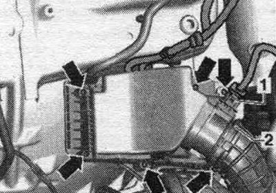
Disconnect the electrical. connect plug "1" to the air flow meter "G70". Open the air duct hose clamp. going to the turbocharger, and pull the hose off the "G70" air flow meter. Loosen the two mounting screws on the "C70" air flow meter and remove it. Carefully remove the "G70" air flow meter from its guide in the air flow meter housing. filter.

Disconnect the electrical. connect plug «1» to the air flow meter «G70». Open the air duct hose…


Install


To ensure the G70 air flow meter functions properly, it is essential to follow these instructions and steps. If the replaceable air element is heavily soiled or saturated with moisture. filters, dirt particles or moisture can get into the G70 air flow meter and distort the data obtained. This will result in a loss of power as less fuel injection volume is calculated. Use only the original filter element. Use grease to install the air duct hose (silicone-free). To secure all hose connections, use clamps of the appropriate series. Check the air flow meter and air duct hose for salt deposits, dirt and leaves (from the clean air intake side). Check the intake duct before the air intake element is replaced. filters for dirt.


If contamination is detected, clean the air duct housing. filter (upper and lower parts) from salt, dirt and leaf deposits (if necessary, wash or vacuum clean). Removal and installation of air. filter. Installation is in reverse order.

Lambda probe


1. Turbocharger: with turbocharger pressure regulator position sensor «G581».

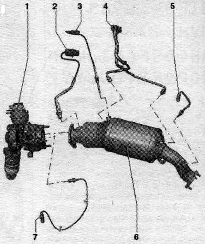
1. Turbocharger: with turbocharger pressure regulator position sensor "G581".
2. Lambda probe "G39" with lambda probe heating element "Z19": new lambda probes are lubricated with mounting paste; on a used lambda probe, lubricate the threads with heat-resistant bolt paste; mounting or heat-resistant paste should not get into the grooves of the lambda probe housing; 50 Nm.
3. Exhaust gas temperature sensor 3 "G495": 45 Nm.
4. Exhaust gas pressure sensor 1 "G450": tighten the bolt to a torque of 4.5 Nm; pressure lines to the diesel particulate filter 45 Nm.
5. Exhaust gas temperature sensor 4 "G648": 45 Nm.
6. Diesel particulate filter: after replacing the diesel particulate filter, it is necessary to make an adjustment, using the Tester for this.
7. Exhaust gas temperature sensor 1 "G235": 45 Nm.


1. Electrical connector of lambda probe «G39» with lambda probe heater «Z19». 2. Fuel temperature…

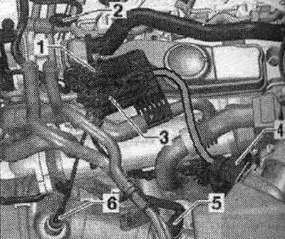
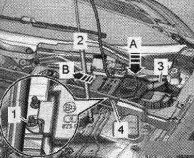
1. Electrical connector of lambda probe "G39" with lambda probe heater "Z19". 2. Fuel temperature sensor "G81". 3. Electrical connector of exhaust gas temperature sensors 3 "G495". 4. Air flow meter "G70". 5. Lambda probe "G39" with lambda probe heating element "Z19". 6. Exhaust gas temperature sensor 3 "G495".


Replacing the engine control unit "J623"


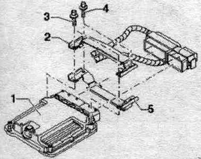
Before removing the engine control unit "J623", the injector adaptation values and soot mass should be read. Use a tester for this. If the injector adaptation values are not read from the old one (faulty) engine control unit, they must be entered into the new engine control unit and adapted manually. After saving the file with the adaptation parameters, turn off the ignition and remove the ignition key. Not every engine control unit is bolted on with a protective housing. The installation of the protective housing depends on the engine-gearbox combination. Protective housing "5" is bolted to engine control unit "1." To prevent loosening of shear screws "4" of retainer "2," a locking varnish is applied to their threads. To be able to remove the plug connectors from the engine control unit (for example, to connect a switch or replace the engine control unit), it is necessary to dismantle the protective housing.

Before removing the engine control unit «J623», the injector adaptation values and soot mass should…


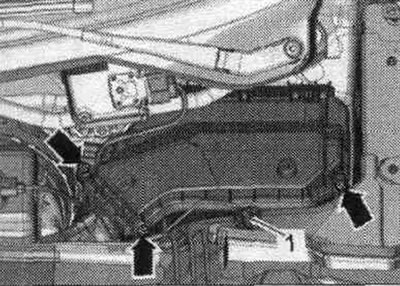
Do not completely remove the rubber seal from the water drain box cover from nut "1." Unscrew nut "1." Disconnect wiring harness "2" from fasteners "A." Remove filler neck "3" with the feed tube from the windshield washer reservoir and the body opening.


Do not completely remove the rubber seal from the water drain box cover from nut «1.» Unscrew nut…


Unscrew the arrow bolts and remove the cover of the switching unit.

Unscrew the arrow bolts and remove the cover of the switching unit.


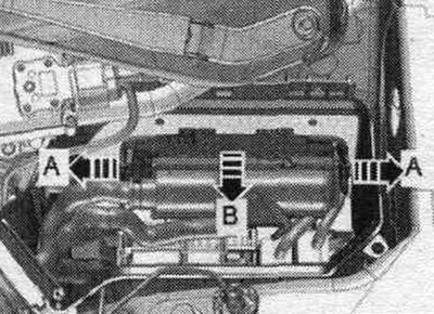
Unlock the clamps "arrow A" and remove the engine control unit "J623" "arrow B".

Unlock the clamps «arrow A» and remove the engine control unit «J623» «arrow B».


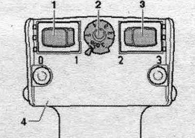
To make it difficult to access the engine control unit connectors, engine control unit "1" is bolted through the locking device "2 and 5" and the locking bolts "3" or "4". On the threads of both locking bolts "4" (not bolted to the engine control unit) thread varnish applied. Therefore, to unscrew these bolts, the threads should be heated with a heat gun. The threads of both locking bolts connected to engine control unit "3" are not protected with thread varnish. The threads in the engine control unit housing must not be exposed to heat (unacceptable heating of the engine control unit). Adjust the hair dryer as shown in the picture. This means that the temperature control potentiometer "2" should be set to maximum heating output, and the two-stage blower intensity switch "3" to position 3.


To make it difficult to access the engine control unit connectors, engine control unit «1» is…


To make it difficult to access the engine control unit connectors, engine control unit «1» is…


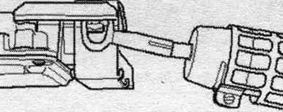
To do this, turn on a hair dryer and heat the bolt for 20-30 seconds. Use pliers to unscrew the locking bolt (in the direction of the arrow).

To do this, turn on a hair dryer and heat the bolt for 20-30 seconds. Use pliers to unscrew the…


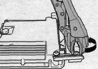
Do not heat the two shear screws screwed into the engine control unit. They should be unscrewed without heating. Disconnect the protective housing from the control unit connectors. Unlock the engine control unit connector and disconnect it. Remove the old engine control unit "J623" and install the new engine control unit "J623".


Install


Installation in reverse order. After this, it is necessary to cover the control unit "J623" with a protective casing. Clean the threaded holes of the locking screws from any remaining thread sealant. A tap can be used for cleaning. Always use new shear screws. Tightening torque for the junction box cover bolts: 3.5 Nm. The steps to be taken after connecting a new engine control unit are described in "Guided Fault Finding" or "Guided Functions." Use the tester for this. After replacing the engine control unit, re-align the fuel quantity adjustment and injector voltage adjustment in the engine control unit "J623." (both parameters affect engine power and exhaust emissions). On vehicles with a diesel particulate filter, the actual mileage must be saved in the engine control unit during approval.

[The original material is located on the website: audimanual.ru]
The article was checked by auto expert Timur Bazhenov
This article is available at russian, bulgarian, belarusian, ukrainian, serbian, croatian, romanian, polish, slovak, hungarian

Share information:
Previous articles
Audi A4 B8: Diesel engines 2.0 l (CA*)
Next articles

Intake manifold, fuel injection pump and injectors — replacement…
Air filter — removal and installation
Fuel system — general description
Injection system overview
Exhaust system (EG) — replacement of components
Exhaust gas recirculation (EGR) system — replacement of…
Glow plugs, speed sensor, and Hall sensor — removal and…


Similar articles on other Audi car models:
Removal and installation the lambda probe Audi 80 B3 (1986-1991)
Removal and installation the metering unit with air flow meter Audi 100 C3 (1982-1990, petrol)
Removal and installation the lower engine compartment cover Audi A3 Type 8L (1996-2003)
Engine Control Unit — Removal and Installation Audi A6 C5 Allroad (1999-2005)
Removal and installation the engine Audi A8 D2 (1994-2002)
Air flow meter, engine control unit, fuel pressure regulator,… Audi Q5 Type 8R (2008-2017)
Removal and installation the engine control unit Audi A2 (1999-2005)
Link to this page in different formats


Visitor comments

No comments yet


How much will 38 + 34 =


A4(B8, 2007-2015) 
  • General information
  • Operating instructions
  • Power unit
  • Petrol engines 1.8 l
  • Petrol engines 1.8/2.0 l
  • Petrol engines 3.0 l
  • Petrol engines 3.2 l
  • Fuel system (petrol)
  • Diesel engines 2.0 l (CA*)
  • Diesel engines 2.0 l (CJCB)
  • Diesel engines 2.7/3.0 l
  • Diesel engines 3.0 l
  • Fuel system (diesel)
  • Transmission
  • Manual gearbox 0B1
  • Manual gearbox 0B2
  • Manual gearbox 0B3
  • Manual gearbox 0B4
  • Automatic transmission 0B5
  • Automatic transmission 0B6
  • Automatic transmission 0AW
  • All-wheel drive system
  • Chassis
  • Front suspension
  • Rear suspension
  • Brake system
  • Steering system
  • Body
  • Exterior
  • Interior
  • Seats
  • Doors, locks and windows
  • Security system
  • Heating and air conditioning
  • Electrical equipment
  • Audio system
  • Power devices
  • Equipment and devices
  • Lighting and lamps
  • Electrical circuits
 
A4(B7, 2004-2008) 
  • General information
  • Introduction to manual
  • Troubleshooting
  • Operating instructions
  • Maintenance
  • Power unit
  • Petrol engines 2.0 (ALT)
  • Petrol engines 2.0 (TFSI)
  • Petrol engines 1.8 (MPI)
  • Diesel engines
  • Cooling system
  • Air conditioner
  • Fuel and exhaust system
  • Ignition system
  • Starting and charging
  • Transmission
  • Clutch
  • Manual gearbox
  • Automatic gearbox
  • Drive shafts
  • Chassis
  • Brake system
  • Front suspension
  • Rear suspension
  • Steering
  • Body
  • Exterior
  • Interior
  • Electrical equipment
  • Equipment and devices
  • Lighting and signaling
  • Windscreen wipers and washers
  • Electrical diagrams
  • Electrical diagrams (since 2007)
 
A4(B6, 2000-2006) 
  • General information
  • Vehicle Description
  • User manual
  • Maintenance
  • Power unit
  • Gasoline engine
  • Diesel engine
  • Lubrication system
  • Cooling system
  • Supply system
  • Injection system
  • Exhaust system
  • Ignition and control
  • Transmission
  • Gear box
  • Clutch and drive shafts
  • Chassis
  • Brake system
  • Car suspension
  • Steering
  • Body
  • Heating and ventilation
  • Exterior (external elements)
  • Interior (internal elements)
  • Electrical equipment
  • Power devices
  • Lighting and appliances
  • Electrical circuits
 
A4(B6, 2000-2006, petrol) 
  • General information
  • Introduction to the guide
  • Car care
  • Power unit
  • Engine repair
  • Lubrication system
  • Cooling system
  • Injection and control system
  • Ignition system
  • Power and exhaust system
  • Transmission
  • Clutch and drive shafts
  • Car gearbox
  • Chassis
  • Suspension and wheels
  • Steering
  • Brake system
  • Body
  • Interior
  • Exterior
  • Electrical equipment
  • Equipment and devices
  • Lighting and signaling
  • Power devices
  • Electrical circuits
 
A4(B5, 1994-2001) 
  • General information
  • Introduction to the guide
  • Car care
  • Maintenance (gasoline)
  • Maintenance (diesel)
  • Power unit
  • Gasoline engines
  • Diesel engines
  • Engine overhaul
  • Cooling system
  • Fuel injection (gasoline)
  • Fuel system (diesel)
  • Exhaust system
  • Ignition system
  • Transmission
  • Clutch
  • Mechanical gearbox
  • Automatic gearbox
  • Drive shafts
  • Chassis
  • Brake system
  • Car suspension
  • Steering
  • Body
  • Exterior
  • Interior
  • Doors, locks and windows
  • Heating and ventilation
  • Electrical equipment
  • Power devices
  • Equipment and devices
  • Electrical circuits
 
A4(B5, 1994-2001, petrol) 
  • General information
  • Vehicle description
  • Maintenance
  • Power unit
  • Engine repair
  • Turbocharging
  • Exhaust system
  • Cooling system
  • Ignition system
  • Fuel system
  • Motronic injection system
  • MPI and MPFI injection system
  • Transmission
  • Clutch
  • Gearbox and shafts
  • Chassis
  • Steering
  • Car suspension
  • Brake system
  • Wheels and tires
  • Body
  • Heating and ventilation
  • Body parts
  • Electrical equipment
  • Fuses and relays
  • Power devices
  • Lighting and lamps
  • Tools and devices
  • Electrical circuits
 
AudiManual.ru © 2017-2026 · Mobile version · Feedback · Sitemap: EN BG BY UA RS HR RO PL SK HU · Site search · News and articles
80 B2 · 80 B3 petrol · 80 B3 · 80 B4 · 100 C3 diesel · 100 C3 petrol · 100 C3 · 100 C4 petrol · 100 C4 · A3 Type 8L · A4 B5 petrol · A4 B5 · A4 B6 petrol · A4 B6 · A4 B7 · A4 B8 · A6 C4 · A6 C5 · A6 C5 Allroad · A8 D2 · Q5 Type 8R · Q7 Typ 4L · Audi A2 ·
This site uses cookies 🍪. Click the button to accept this fact.