
Table of contents: Charge air cooling system ↓ Removal and installation the charge… ↓ Removal and installation of the… ↓
Turbocharger
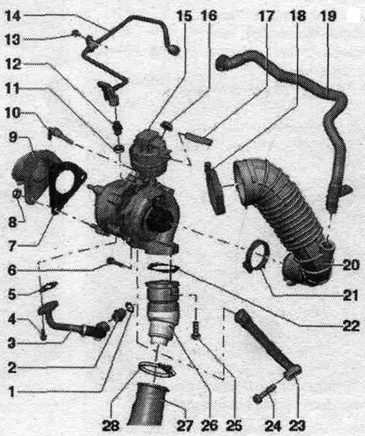
1. Lip seal: replace.
2. Connecting pipe: 40 Nm.
3. Return oil line: to the cylinder block; tighten the union nut to a torque of 40 Nm.
4. Bolt: 15 Nm; bolts of strength class 10.9; use only original bolts.
5. Gasket: replace.
6. Bolt: 20 Nm.
7. Gasket: replace.
8. Bolt: 23 Nm; replace.
9. Diesel particulate filter with catalytic converter.
10. Exhaust gas temperature sensor 1 "G235".
11. Lip seal: replace.
12. Connecting pipe: 30 Nm.
13. Bolt: 10 Nm.
14. Oil supply line: tighten the union nuts to a torque of 22 Nm.
15. Turbocharger.
16. Nut: 25 Nm; bolted connection of the turbocharger to the exhaust manifold; replace; lubricate with heat-resistant paste; heat-resistant paste.
17. Vacuum hose: electromagnetic turbocharger pressure limiting valve "N75".
18. Hose clamp: 3.5 Nm.
19. Engine crankcase ventilation hose.
20. Air duct hose.
21. Hose clamp: 3.5 Nm.
22. Gasket: replace if damaged or leaking.
23. Support.
24. Bolt: 40 Nm.
25. Bolt: 10 Nm.
26. Support.
27. Air duct to the intercooler.
28. Hose clamp: 3.5 Nm.
Take off
Caution! If the turbocharger has mechanical damage (for example, damage to the impeller), it is not enough to simply replace the turbocharger. To prevent further damage, the following steps must be taken. Check the housing and air filter element. filters, as well as air supply hoses for contamination. Check the entire system. charge air supply and intercooler for foreign objects. If in the system. if foreign bodies are detected in the air boost line, clean the air boost lines and replace the intercooler if necessary.
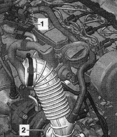
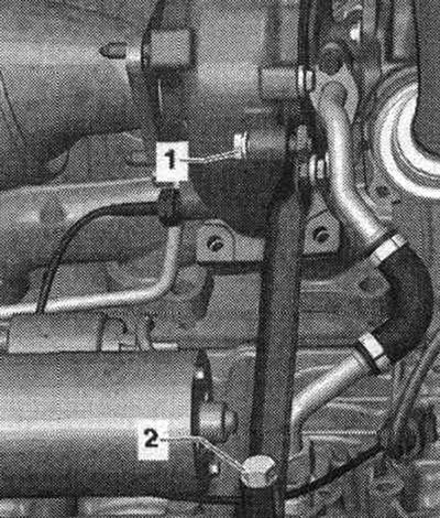
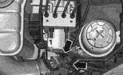
Remove the "arrow" engine cover. Remove the air intake housing. filter. Move aside and release the engine crankcase ventilation "1". Loosen the clamp for the hose "2", remove and take out the air duct hose. Remove sound insulation. Remove the exhaust pipe.
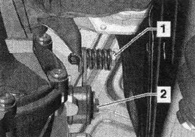
Disconnect bolt connection "1", unscrew bolt "2" and remove the diesel particulate filter suspension mount.
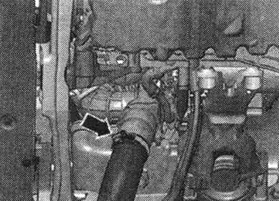
Disconnect the hose clamp "arrow", remove the air duct hose and set it aside.
Unscrew bolts "1" and "2", remove the support.
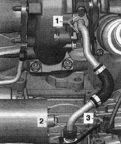
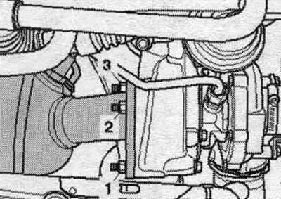
Unscrew bolts "1" and union nut "2", remove the oil drain line. Disconnect electrical connector "3" of exhaust gas temperature sensor 1 "G235" and disconnect it from the bottom of the engine block.
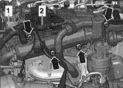
Remove vacuum hose "1". Unscrew bolts "2" and "4".
Do not unscrew lines "1" and "2". Unscrew the "arrow" bolts and tie up the system cooler. exhaust gas recirculation.
Unscrew nuts "1...3" on the turbocharger. In vehicles with independent heating, nut "1" is accessible from below.
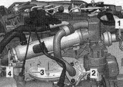
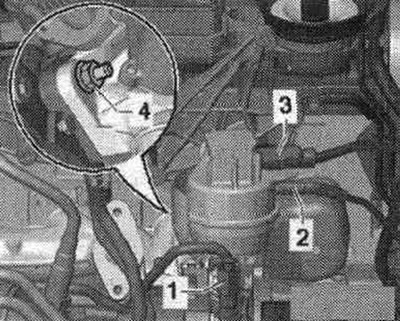
Loosen union nut "1". Remove vacuum hose "2". Disconnect connector "3" of the boost pressure regulator position sensor "G581". Unscrew nut "4" securing the turbocharger to the exhaust manifold.
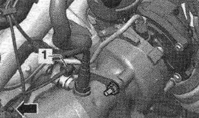
Disconnect the electrical wire on the engine block "arrow".
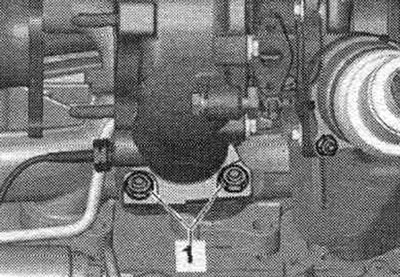
Unscrew nuts "1" and remove the turbocharger. To prevent dirt from entering, seal open lines and pipes on the turbocharger with clean plugs or protective caps. To avoid damage, do not place the removed turbocharger on top of the oil return line.
Installation
Installation in reverse order. Replace gaskets, o-rings and seals. o-rings. During installation, install all thermal insulation cuffs in their original locations. Fill the turbocharger with oil through the oil supply line nipple. Hoses and hose fittings syst. air boosters must be cleaned of oils and grease before installation. Secure all hose connections with hose clamps of the appropriate series. For secure fastening of hoses
charge air at the fittings should be In order to ensure that oil is supplied to the turbocharger, the engine should be run for approx. after installing the turbocharger. 1 minute at idle speed; do not give the engine high revs.
Charge air cooling system
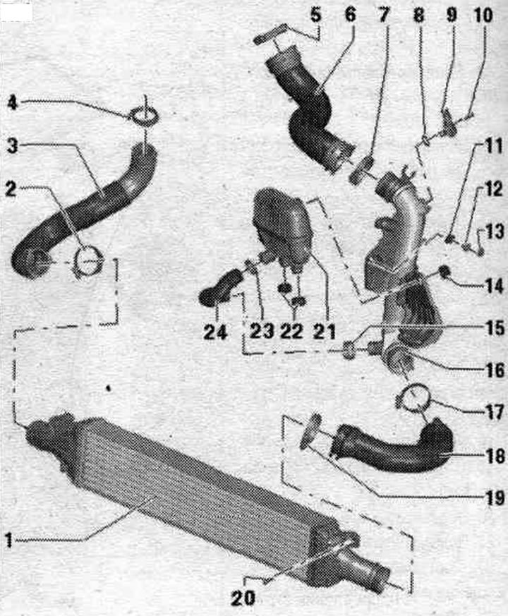
1. Intercooler.
2. Hose clamp: reinforced; 5.5 Nm.
3. Air duct hose; to the turbocharger; before installation, clean from oil and grease.
4/5. Hose clamp: reinforced; 5.5 Nm.
6. Air duct hose: to the intake manifold; before installation, clean from oil and grease.
7. Hose clamp: reinforced; 5.5 Nm.
8. Sealing ring: replace.
9. Boost pressure sensor "G31".
10. Bolt; 5 Nm.
11. Rubber tip.
12. Bushing.
13. Nut: 9 Nm.
14. Rubber tip.
15. Hose clamp: reinforced; 5.5 Nm.
16. Air guide tube.
17. Hose clamp: reinforced; 5.5 Nm.
18. Air duct hose: from intercooler; before installation, clean from oil and grease.
19. Hose clamp: reinforced; 5.5 Nm.
20. Bolt: 7 Nm.
21. Resonator.
22. Rubber tip.
23. Hose clamp: reinforced: 5.5 Nm.
24. Air duct hose: to the resonator; before installation, clean from oil and grease.
Removal and installation the charge air radiator
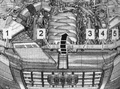
Remove the bolts "1, 2, 3, 5". Remove cover "4" of the radiator frame and hang it on the radiator grille "arrow".
Loosen the "arrow" bolts. Remove the air duct "1" from the intermediate flange "2" of the air duct housing. filters. For all-wheel drive vehicles, remove the front bumper.
Unscrew bolts "1" and "2" and remove the noise insulation screen of the bumper lining in the rear direction.
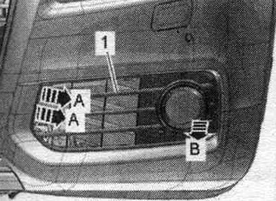
Unlock the retaining clips "arrows A" and remove the air intake grille "1" on the left and right from the lower part of the bumper trim "arrow B". For better visualization, the installation position is shown in the following illustrations with the bumper removed.
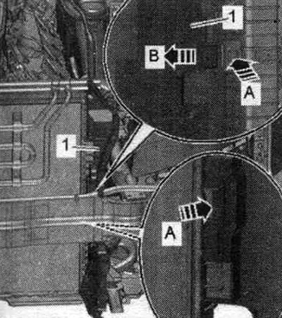
Release the clamps "arrow A" and tilt the air duct "1" on the left and right towards the center of the car "arrow B".
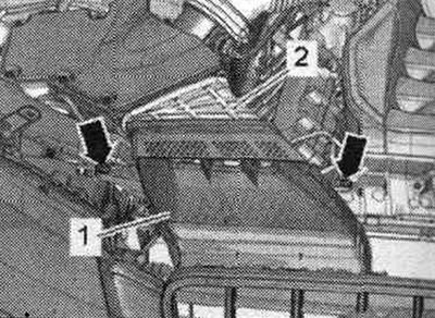
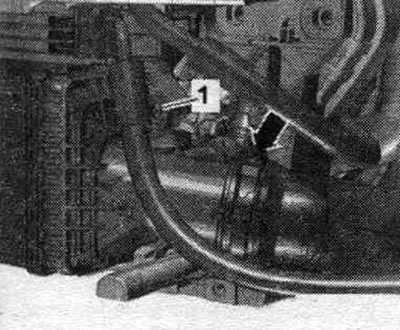
Remove the air duct hose from the intercooler by loosening the hose clamp "arrow". Unscrew bolt "1".
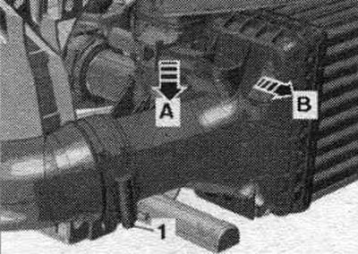
Remove the air duct hose from the intercooler by loosening the hose clamp "1". Press the clamp down "arrow A" and slightly tilt the top of the intercooler "in the direction of arrow B".
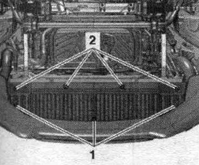
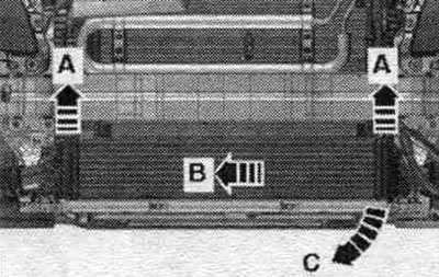
Remove the intercooler from the radiator upwards "arrows A" and push it "in the direction of arrow B". Grasping from the left side, remove the intercooler downwards "arrow C".
Installation in reverse order. For all-wheel drive vehicles, install a front bumper.
Removal and installation of the charge pressure sensor "G31"
Disconnect the "1" connector of the "G31" boost pressure sensor. Remove the "arrow" bolts and pull out the boost pressure sensor
"G31" from the air guide pipe.
Installation in reverse order. Replace the seal. ring.