



Note: Remove the engine without the gearbox in an upward direction. During installation, all cable ties should be placed in their original locations. To be able to rotate the driveshaft on a four-wheel drive vehicle for removal, the power must be turned off before disconnecting the battery. mechanical parking brake. Observe precautions when disconnecting the battery. Disconnect the battery. Remove the front wheels: right and left. Remove the front right and left fender liner. Remove sound insulation. Remove the exhaust pipe. Bring to server. position. Remove the air casing. filter. Remove the "arrow" engine cover.
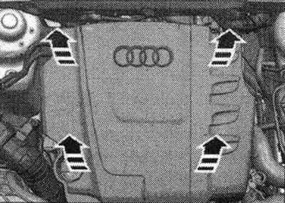
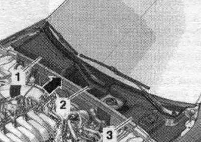
Remove the "arrow" gasket. Disconnect and remove gaskets "1, 2, 3" from the water drainage box cover.
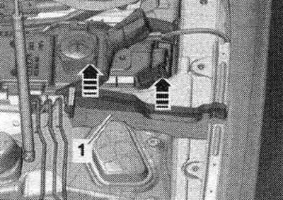
Remove the left and right elements "1" from the foam upwards in the direction of the "arrows".
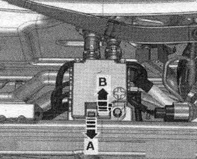
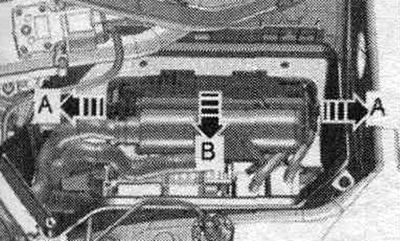
Unlock the lock "arrow A" and open the cover "arrow B".
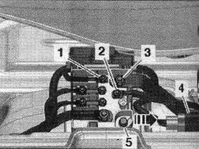
Loosen the nuts on wires "1...3." Remove plug connection "4" from its holder and disconnect it. Unscrew "5" and remove the wire distributor from the "arrow" stretcher.
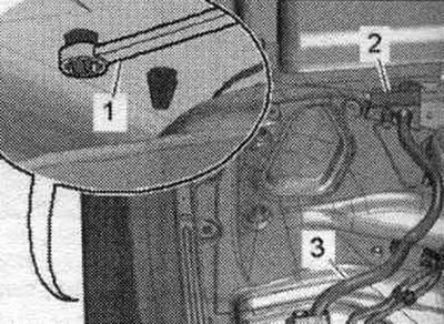
Unlock the retainers from the wheel arch using a 5.5 open-end wrench "pos. 1" and remove the cable entry "2" upwards.
Open the cable channel by unlocking the lock "arrow B", pull the cable channel forward "arrow A" and release the wires.
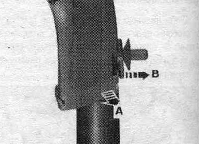
Unscrew the nut "1" and tilt the filler neck of the washer fluid reservoir slightly upwards "arrow A". Remove the filler neck "2" with the filler tube from the washer fluid reservoir, passing it through the body opening "arrow B".
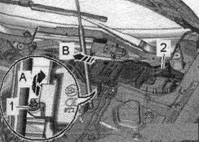
Unscrew bolts "1" and nuts "2" and remove stretcher "3".
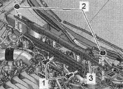
Unscrew the arrow bolts and remove the cover of the motorcycle switching unit. compartment. Unscrew nut "1" and release the wire.
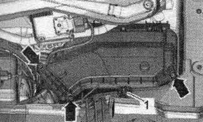
Remove the fasteners "arrow A" and open the cover "arrow B" of the engine control unit.
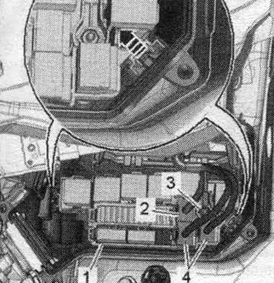
Disconnect the plug connectors "4" and unscrew the nut "3" securing the wire. If present, disconnect connector "2". Remove the "arrow" clips and the fasteners for the relay with fuse holder "1".
Unlock the clamps "arrow A" and remove the cable guide "1" in the upward direction "arrow B". Disconnect the engine wiring harness from the switch. block in motorcycle. compartment and release it. Place the wiring harness on the engine and secure the engine control unit from falling out.
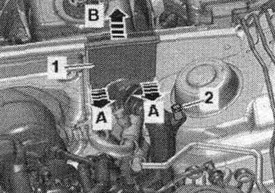
Open the expansion lid. tank. Install a tray for service cranes under the engine. Open drain valve "1" on the connecting fitting and drain the coolant, then remove fitting "2" from the radiator.
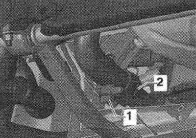
Unscrew nuts "3" on the left and right and remove longitudinal rods "2".
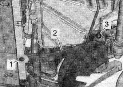
Unscrew bolts "1" and remove the front support of the power unit. Unscrew bolts "2" on the left and right, remove crossbar "3".
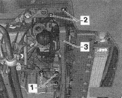
Disconnect the hose clamp "arrow", remove the air duct hose and set it aside.
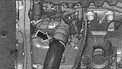
Unscrew nut "2" of the bracket with electrical wiring on the right side of the car.
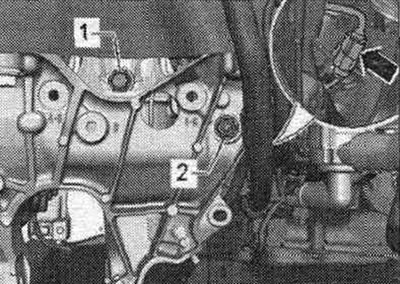
Unscrew the "arrow" nut on the right side member and release the ground cables.
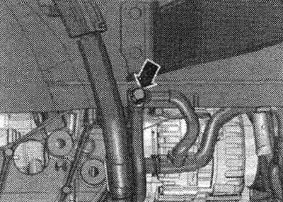
Disconnect the electrical connector "1" of the radiator fan, move the lock back "arrow" and press the stopper down. Place the wiring harness on the engine and secure it from falling.
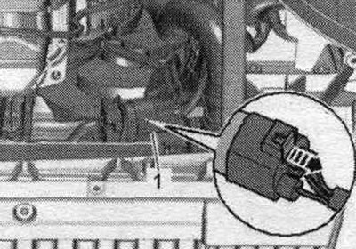
Remove the vacuum pipe "1" from the end wall of the water drainage box; to do this, disconnect the vacuum hose "2" on the rear side of the "arrow".
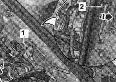
Unscrew nut "5". Remove coolant hoses "1...4" and remove the end wall of the water drainage box.
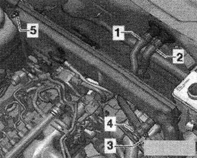
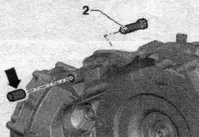
Unscrew bolts "2...6". Bolt "2" secures the starter to the gearbox and has an additional. the "arrow" spacer sleeve. When removing and installing the engine, remember to use the "arrow" spacer sleeve. The spacer sleeve must be installed between the starter and the transmission.
Remove the system hose. cooling "2" and constant ventilation "1".
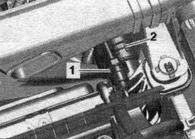
Disconnect the permanent ventilation "1" and the system hose. cooling "2" from expansion. coolant reservoir.
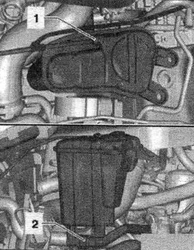
Release the "arrow" hose clamps and remove the air duct hose. Disconnect and release the plug connector of the boost pressure sensor "G31" "1".
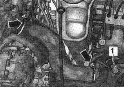
Disconnect and release the plug connectors "1" of the lambda probe "G39" and connectors "2" of the exhaust gas temperature sensor 3 "G495". Disconnect connector "3" of the exhaust gas pressure sensor 1. Unscrew bolt "4", unlock the air hoses of the exhaust gas pressure sensor 1.
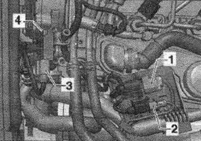
Unscrew nut "1" and remove holder "2".
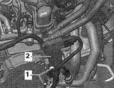
Unscrew nuts "1...3" on the turbocharger. In vehicles with independent heating, nut "1" is accessible from below.
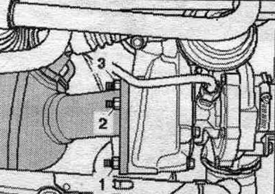
Release the arrow clamps and remove the timing belt protective cover.
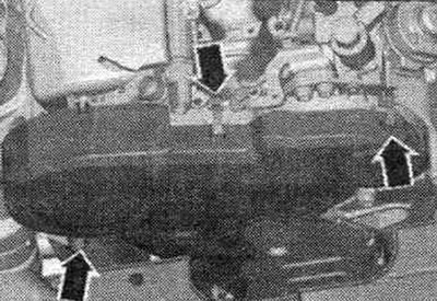
Before removing the poly V-belt, mark the direction of travel with chalk or a felt-tip pen. Changing the direction of a previously used belt may cause damage to it. Turn the tensioner in the direction of the arrow, remove the poly V-belt from the alternator pulley, and secure the tensioner with the T40098 clamp. Remove the poly V-belt.
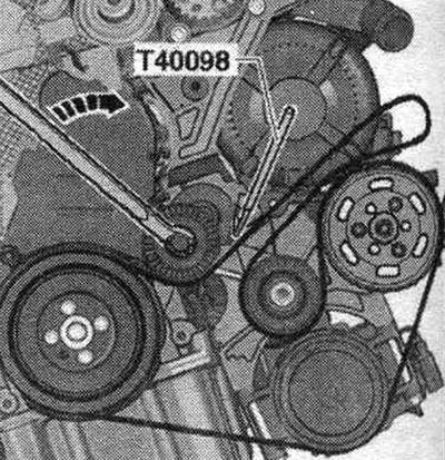
Unscrew the arrow bolts and remove the belt pulley.
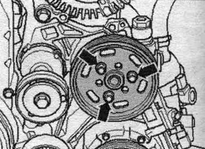
Unscrew the "arrow" hydraulic pump and tie it to the side, the pipes remain connected.
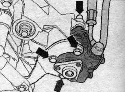
Disconnect the supply "1" and return "2" fuel lines.
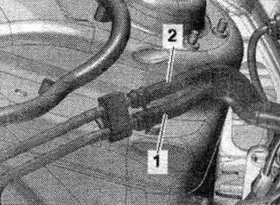
Disconnect and release the connectors "1, 2, 3." Loosen the "arrow" bolts and tie the air conditioner compressor to the side; the tubes remain connected.
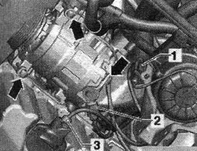
Support the gearbox using a tilter and a mounted gearbox support.
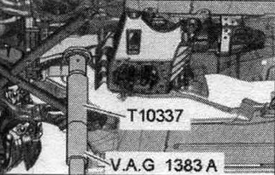
Unscrew the tunnel cross member arrow bolts.
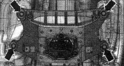
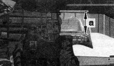
Lower the CP using a tilting device by the dimension "a". Dimension "a" = maximum 80 mm.
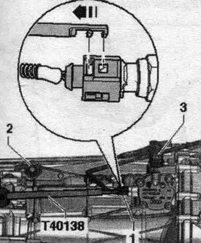
Disconnect and release the plug connector "1" of the reversing light switch "F4" using the puller "T40138".
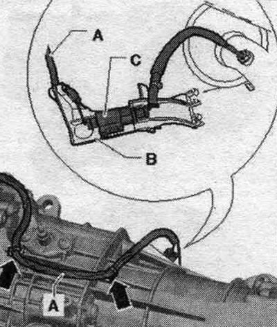
Unlock the electrical wire "A" from the gearbox and disconnect the electrical connector "C".
Raise the gearbox with a tilting device and screw in the tunnel crossmember arrow bolts.
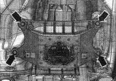
Remove cover "1" from the bottom of the "arrow" gearbox.
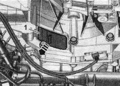
Remove 3 bolts "arrow" of the driven disk. To do this, turn the crankshaft 120° in the direction of engine rotation.
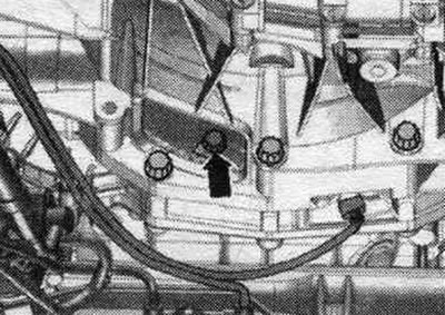
Unscrew bolt "1" of the starter from the engine side. Remove the starter from the gearbox, place it on the engine support and secure it to prevent it from falling. The starter cannot be removed. Therefore, when installing the engine, the starter must be installed in place before connecting it to the gearbox using flanges. Loosen the remaining bolts "7...10" securing the engine to the gearbox. Install the "10-222 A" crossmember with the "10-222 A/8" legs on the shock absorber cups on the left and right, as shown in the figure. Connect the gearbox and lead screw with a "10-222 A/12" weight clamp. Shown with the engine removed for better clarity. Slightly pre-tension the spindles of the 10-222 A crosshead!
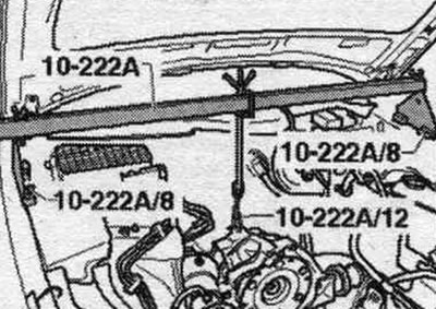
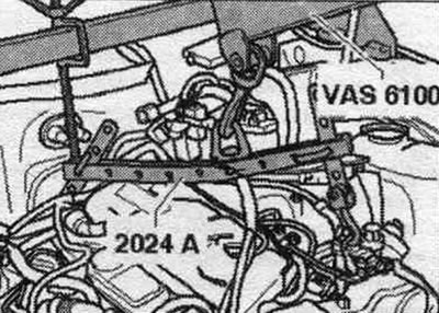
Hang the "2024 A" lifting device on the engine and on the "VAS 6100" service crane as shown in the figure.
Unscrew bolts "1" of the engine mounts on the left and right. Check that all hoses and wires between the engine and the body are disconnected.
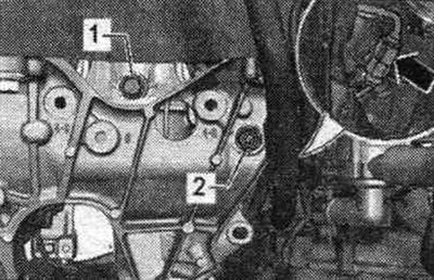
Raise the engine enough to clear the engine mounts. Tighten the lead screw of the 10-222 A crosshead. Disconnect the engine from the gearbox and remove it upwards from the engine. compartment.
The original publication in its entirety is posted on the website AUDIMANUAL