
Table of contents: Control unit ↓ Central injection system ↓ Injector ↓ Air temperature sensor ↓ Pressure regulator ↓ Throttle positioner ↓ Throttle potentiometer ↓ Functioning of the injection system ↓ Cold engine ↓ Idling ↓ Acceleration motion ↓ Full load ↓ Coasting ↓ Engine speed limitation ↓
Control unit
It is located on the right side of the gutter and receives information from the following parts via a multi-pin plug:
- From the Hall sensor in the ignition distributor about the engine speed.
- From the lambda probe in the front exhaust pipe about the oxygen content in the exhaust gases.
- From the throttle position potentiometer and the amount of incoming air.
- From the temperature sensor at the inlet of the injection system about the temperature of the incoming air.
- From the temperature sensor on the coolant pipe at the front of the cylinder head about the coolant temperature.
From all these signals, the control unit calculates the duration of the opening of the injector, controlled by the electromagnet, and with it the amount of fuel injected. In doing so, the control unit accesses the engine data memory unit, which stores data on the possible engine states. It also contains information on the required amounts of fuel - naturally, in the form of electrical signals. If the Monomotronic system is present, the control unit stores information on the amount of fuel and the ignition timing corresponding to the given operating state.
Central injection system
Most of the central injection system components are assembled in one housing. It not only looks like a carburetor, but also has a throttle valve, which is moved by the gas pedal. The incoming air passes through the housing and here fuel is added to it by means of an injector, just like in a carburetor.
Injector
It is opened by an electromagnet. Thus, the fuel can flow or not, according to the signal from the control unit. In order for the fuel to be atomized in the best possible way, the injector has beveled outlet holes, through which the fuel is sprayed onto the conical surface of the outlet hole and forms a swirl there.
Air temperature sensor
It is located on the side of the injector body and measures the temperature of the air entering the injection system.
Pressure regulator
It ensures a constant fuel pressure of 1 bar at the injector. To do this, it diverts more or less fuel back into the fuel tank. The fuel supply is maintained constant.
Throttle positioner
A small electric motor with a bevel gear moves the pushrod closer to or further from the idle stop of the throttle valve. As a result, the throttle valve can open more or less. This allows the idle speed to be maintained constant under various loads. At the front of the throttle positioner pushrod is a switch that notifies the control unit that the gas pedal has been released.
Throttle potentiometer
It informs the control unit about the throttle valve movements and its position. Thus, for example, the control unit "learns" about a sharp press on the "gas" pedal. The potentiometer is nothing more than a variable resistance.
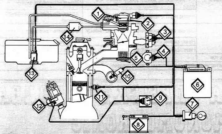
Schematic representation of the injection system and its components
1 Injection system
2 Air temperature sensor
3 Throttle positioner
4 Throttle potentiometer
5 Heating element of the intake pipe heating system
6 Bloch management
7 ignition starter switch
8 Battery
9 Transistor ignition system switch
10 Lambda probe
11 Coolant temperature sensor
12 Ignition distributor
13 Electric fuel pump
Functioning of the injection system
The fuel pump supplies fuel under pressure to the pressure regulator, which ensures a constant pressure at the injector (1 bar).
The control unit receives information about the engine operation in the form of pulses from the ignition system and the resistance value of the throttle potentiometer (throttle position). From this, the control unit draws a conclusion about the engine load value and mixes (via injector) the required amount of fuel with the incoming air. In this mixing, it is important that the fuel-air ratio is correct (1=1) for optimal operation of the catalytic converter. This ratio is adjusted according to the signal from the lambda probe.
The injector can only open and close, but not dose the amount, so the amount of fuel supplied during one injection varies. This happens as follows: with each impulse from the ignition system, the injector makes one injection. If a small amount of fuel is required, the injector opens with this impulse for a very short time - less than one thousandth of a second.
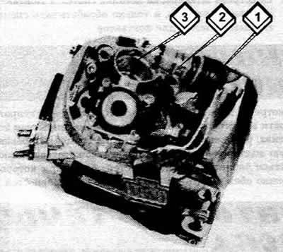
The injector (2) with the connected plug (1) is removed from the socket (3) of the injection system. The mesh fuel filter is visible on the side of the injector
If the engine needs more fuel (when cold or under full load), injection takes longer. This is repeated with each ignition pulse.
Cold engine
The control unit receives information about the engine temperature from the coolant temperature sensor. The colder the engine, the longer the injection time to create a richer mixture. In this mode, the lambda signal is not taken into account, since it is not possible to create a mixture that is optimal for the operation of the catalyst.
Idling
The switch on the throttle positioner informs the control unit of this operating mode. The throttle positioner regulates the idle speed.
At the same time, the switch disables the two-way valve. Thus, vacuum no longer flows to the distributor to regulate the ignition advance. When the vacuum regulation of the ignition advance is disabled, the ignition timing shifts slightly to the "later" side, which improves the composition of the exhaust gases.
Acceleration motion
The control unit recognizes the sudden supply of "gas" thanks to the signal from the potentiometer as the beginning of acceleration, as a result of which the mixture is immediately enriched.
Full load
At full throttle, or more precisely at a throttle position of 72.5°, the control unit ensures the mixture enrichment required for full load mode. Thus, the proportion shifts towards increasing fuel. The potentiometer informs about the throttle position. In this mode, the lambda signal is ignored.
Coasting
Downhill driving with the "accelerator" pedal released saves fuel because the fuel supply is cut off. The control unit recognizes this mode by releasing the "accelerator" pedal (throttle shaft switch) and high engine speed.
Engine speed limitation
When the maximum speed is exceeded, the control unit interrupts the fuel supply to protect the engine from overload. Speed limitation on vehicles with a catalytic converter cannot be achieved by turning on the ignition, since unburned fuel will then enter the catalytic converter. This can lead to its heating to a dangerous temperature and damage.
[The original article is available on the online resource «AUDImanual»]