
Repair Chevrolet Repair Toyota Repair Honda Repair AvtoVAZ Repair Mercedes-Benz Repair BMW Repair Opel
Home  |  Contacts  |  Sitemap  |    
English Русский
Български
Беларускі
Український
Српски
Hrvatski
Română
Polski
Slovenský
Magyar
AudiManual.ru


  • AUDI 80
  • AUDI 100
  • AUDI A3
  • AUDI A4
  • AUDI A6
  • AUDI A8
  • AUDI Q
  • OTHER
  • ARTICLES
C4 (1990-1994) C4 (1990-1994, petrol) C3 (1982-1990) C3 (1982-1990, petrol) C3 (1982-1990, diesel)

KE-Motronic injection system parts (Audi 100 C4)

  • Home
  • Audi 100
  • C4 (1990-1994)
  • Power unit
  • Fuel system (gasoline)
  • KE-Motronic injection system parts
            0
Table of contents: Throttle valves ↓ Mixture regulator ↓ Pressure regulator ↓ Injectors ↓ Pressure regulator ↓ Injectors ↓

Throttle valves


In one of the intake manifold pipes there are two throttle valves. The smaller of these valves is connected by a cable to the gas pedal in the car. It regulates the air supply to the engine up to about half the gas pedal stroke. When the gas pedal is pressed further, the drive opens the second, larger valve. When the pedal is fully pressed, both throttle valves are fully open.

Mixture regulator


This is one of the main parts of the injection system, includes an air quantity meter and a fuel dispenser. They function as follows:
  • The light metal plate of the air quantity meter is located along the air flow to the engine. This plate is lifted during the piston stroke during the intake stroke and the more the more air needs to be supplied to the throttle valve. The amount of rotation of the plate is transmitted to the fuel dispenser using a system of levers.
  • The fuel metering device consists mainly of a distribution piston and a housing with slots. For each engine cylinder, the housing has its own slot, through which the fuel flows to the corresponding injector. The distribution piston closes or opens the slot more or less and, in accordance with the position of the air-measuring plate, passes the required amount of fuel.
  • System pressure: The fuel pump supplies fuel under pressure to the injection system. The first stage of the pressure regulator is located here in a separate housing. It releases excess pressure and leaves a pressure of 6.6 bar in the fuel system. This pressure is present in the dispenser, fuel lines and injectors.


Pressure regulator


The pressure regulator, together with the vacuum chambers, determines the amount of mixture. This is done with the help of pressure differential valves, which usually perform a different task. Fuel supply to the vacuum chambers (from which the required amount of mixture comes out) is carried out using a pressure regulator. If it passes a lot of fuel to the vacuum chambers, the pressure inside the chambers increases, causing the membranes of the pressure differential valves to bend in the direction of the valve openings. Less fuel is supplied to the injectors. The reverse action occurs in the same way. The pressure regulator receives control signals from the control unit. In this case, lambda regulation, temperature and engine load are taken into account. The pressure regulator is located on the side of the mixture regulator.

Injectors


They inject fuel into the fuel channel in front of the inlet valve of the corresponding cylinder until the fuel pressure reaches 3.7-4.8 bar (depending on the engine type) At the same time, they open up to 200 times per second, thanks to which the fuel can be atomized particularly finely.
Pressure regulator


The pressure regulator, together with the vacuum chambers, determines the amount of mixture. This is done with the help of pressure differential valves, which usually perform a different task. Fuel supply to the vacuum chambers (from which the required amount of mixture comes out) is carried out using a pressure regulator. If it passes a lot of fuel to the vacuum chambers, the pressure inside the chambers increases, causing the membranes of the pressure differential valves to bend in the direction of the valve openings. Less fuel is supplied to the injectors. The reverse action occurs in the same way. The pressure regulator receives control signals from the control unit. In this case, lambda regulation, temperature and engine load are taken into account. The pressure regulator is located on the side of the mixture regulator.


Injectors


They inject fuel into the fuel channel in front of the inlet valve of the corresponding cylinder until the fuel pressure reaches 3.7-4.8 bar (depending on the engine type) At the same time, they open up to 200 times per second, thanks to which the fuel can be atomized particularly finely.

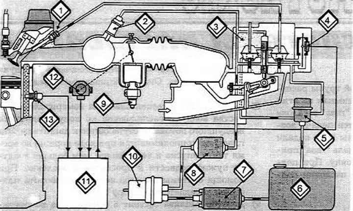
KE-Motronic injection system diagram

KE-Motronic injection system diagram

1 Injector
2 Cold start valve
3 Mixture regulator
4 Pressure regulator
5 Diaphragm pressure regulator
6 Fuel tank
7 Electric fuel pump
8 Filter
9 Idle speed stabilization valve
10 Fuel accumulator
11 Control unit
12 Switch on the throttle shaft
13 Coolant temperature sensor
The article was checked by auto expert Georgy Rodionov
This article is available at russian, bulgarian, belarusian, ukrainian, serbian, croatian, romanian, polish, slovak, hungarian

Share information:
Previous articles
Audi 100 C4: Fuel system (gasoline)
Next articles

Air filter
Fuel tank sensor
Fuel filter
Electric fuel pump
Functioning of the KE-Motronic injection system
Self-diagnosis of faults in the KE-Motronic injection system
Troubleshooting individual components of the KE-Motronic…
Removal the injector of the KE-Motronic injection system


Similar articles on other Audi car models:
Fuel injection system parts — removal and installation Audi 80 B3 (1986-1991, petrol)
Fuel injection system device (petrol) Audi A3 Type 8L (1996-2003)
This is how the Motronic injection system works Audi A4 B5 (1994-2001, petrol)
Motronic/Jetronic fuel injection system components Audi A6 C4 (1994-1997)
General information about the ignition and fuel injection system Audi A8 D2 (1994-2002)
Injection system Audi Q5 Type 8R (2008-2017)
General information about the fuel injection system Audi A2 (1999-2005)
Link to this page in different formats


Visitor comments

No comments yet


How much will 27 + 33 =


100(C4, 1990-1994) 
  • General information
  • User manual
  • Power unit
  • Engine repair
  • Ignition system
  • Fuel system (gasoline)
  • Fuel system (diesel)
  • Lubrication system
  • Cooling system
  • Exhaust system
  • Transmission
  • Clutch
  • Car gearbox
  • Drive shafts
  • Chassis
  • Car suspension
  • Steering
  • Wheels and tires
  • Brake system
  • Body
  • Ventilation and heating
  • Body repair
  • Electrical equipment
  • Power devices
  • Lighting and appliances
  • Electrical circuits
 
100(C4, 1990-1994, petrol) 
  • General information
  • Operation and maintenance
  • Power unit
  • Engine repair
  • Exhaust system
  • Cooling system
  • Supply system
  • Air filter
  • Mono-Motronic injection system
  • Digifant injection system
  • KE-III-Jetronic and KE-Motronic
  • MPI and MPFI injection system
  • Transmission
  • Clutch
  • Car gearbox
  • Chassis
  • Suspension and steering
  • Brake system
  • Wheels and tires
  • Body
  • Exterior
  • Interior
  • Electrical equipment
  • Fuses and relays
  • Power devices
  • Ignition system
  • Lighting and signaling
  • Equipment and devices
  • Electrical circuits
 
100(C3, 1982-1990) 
  • General information
  • User manual
  • Maintenance
  • Specifications
  • Power unit
  • Engines 4-cylinder
  • Engines 5-cylinder
  • Diesel engine
  • Cooling system
  • Power system (carburetor)
  • Power system (injector)
  • Fuel system (diesel)
  • Transistor ignition system
  • Electronic ignition system
  • Transmission
  • Clutch
  • 4 speed gearbox 014
  • 5 speed gearbox 013 and 093
  • 5 speed gearbox 016 and 012
  • Shift mechanism KP 016
  • Automatic transmission
  • Front wheel drive
  • Chassis
  • Front suspension
  • Rear suspension
  • Steering
  • Brake system
  • Body
  • Body elements
  • Electrical equipment
  • Lighting and appliances
  • Power devices
  • Electrical circuits
 
100(C3, 1982-1990, petrol) 
  • General information
  • Maintenance and operation
  • 4 cylinder engine
  • Engine repair
  • Cooling and lubrication system
  • Supply system
  • Ignition system
  • 5 cylinder engine
  • Engine repair
  • Cooling and lubrication system
  • Supply system
  • Ignition system
  • Transmission
  • Clutch and drive shafts
  • 4 speed gearbox 014
  • 5 speed gearbox 013 and 093
  • 5 speed gearbox 016 and 012
  • Automatic gearbox
  • Chassis
  • Steering
  • Front suspension
  • Rear suspension
  • Brake system
  • Body
  • Body elements
  • Doors, locks and windows
  • Body repair
  • Electrical equipment
  • Equipment and devices
  • Power devices
  • Electrical circuits
 
100(C3, 1982-1990, diesel) 
  • General information
  • User manual
  • Maintenance
  • Troubleshooting
  • Power unit
  • Engine in a car
  • Engine removed
  • Cooling system
  • Fuel system
  • Exhaust system
  • Starting and charging
  • Preheating
  • Transmission
  • Clutch
  • Mechanical gearbox
  • Automatic gearbox
  • Drive shafts
  • Chassis
  • Brake system
  • Suspension
  • Steering
  • Body
  • Exterior
  • Interior
  • Electrical equipment
  • Equipment and devices
  • Electrical circuits
 
AudiManual.ru © 2017-2026 · Mobile version · Feedback · Sitemap: EN BG BY UA RS HR RO PL SK HU · Site search · News and articles
80 B2 · 80 B3 petrol · 80 B3 · 80 B4 · 100 C3 diesel · 100 C3 petrol · 100 C3 · 100 C4 petrol · 100 C4 · A3 Type 8L · A4 B5 petrol · A4 B5 · A4 B6 petrol · A4 B6 · A4 B7 · A4 B8 · A6 C4 · A6 C5 · A6 C5 Allroad · A8 D2 · Q5 Type 8R · Q7 Typ 4L · Audi A2 ·
This site uses cookies 🍪. Click the button to accept this fact.