
Repair Chevrolet Repair Toyota Repair Honda Repair AvtoVAZ Repair Mercedes-Benz Repair BMW Repair Opel
Home  |  Contacts  |  Sitemap  |    
English Русский
Български
Беларускі
Український
Српски
Hrvatski
Română
Polski
Slovenský
Magyar
AudiManual.ru


  • AUDI 80
  • AUDI 100
  • AUDI A3
  • AUDI A4
  • AUDI A6
  • AUDI A8
  • AUDI Q
  • OTHER
  • ARTICLES
C4 (1990-1994) C4 (1990-1994, petrol) C3 (1982-1990) C3 (1982-1990, petrol) C3 (1982-1990, diesel)

Electric fuel pump (Audi 100 C4)

  • Home
  • Audi 100
  • C4 (1990-1994)
  • Power unit
  • Fuel system (gasoline)
  • Electric fuel pump
            0
Table of contents: Checking the fuel pump ↓ Replacing the fuel pump ↓
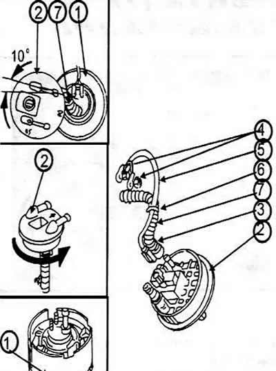
1 Inner part of the fuel intake housing

1 Inner part of the fuel intake housing
2 Connecting flange
3 Fastening clamps
4 Fastening bolt
5 Wire
6 Wire clamp
7 Fuel hose


The fuel pump is mounted on the underside of the fuel tank. A relay supplies voltage to the pump. A safety switch is installed to ensure that the pump only supplies fuel when the engine is running.

Checking the fuel pump


If the pump is not working properly or it is suspected that the fuel supply is insufficient, some operations can be carried out to check the pump operation. Some experience with electrical equipment is also necessary. It is assumed that the corresponding fuse is OK. This is fuse #17 in the fuse box.

To check the main pump activation, you need to raise the rear of the car, support it on stands and listen near the fuel tank to see if the fuel pump clicks when an assistant turns on the ignition. If it does, determine where the fuel is remaining.

Place a rag under the threaded connection of the fuel lines and loosen the connection. If fuel sprays out, this is a sign that the fuel system is under pressure. If this is not the case, then turn on the starter. Now the fuel should spray out. If this does not happen:


Remove the boot floor trim and unscrew the black cover. Remove the multi-pin plug and check with a test lamp or voltmeter whether there is voltage between the two contacts, i.e. those to which the brown and yellow/green wires are connected. To do this, turn on the starter. The described check shows that voltage is supplied to the pump. If there is no voltage, it can be assumed that the pump needs to be replaced.

Before replacing the pump, you need to check the pump relay.

Replacing the fuel pump


The fuel pump is specially reinforced and a special key (3307) is required to remove it. If this key is available, the pump is removed together with the inner part of the fuel intake housing.

Caution: The fuel tank may be no more than ⅔ full at the time the pump needs to be removed.


Fold back the trunk floor trim and remove the black metal cover (arrows).
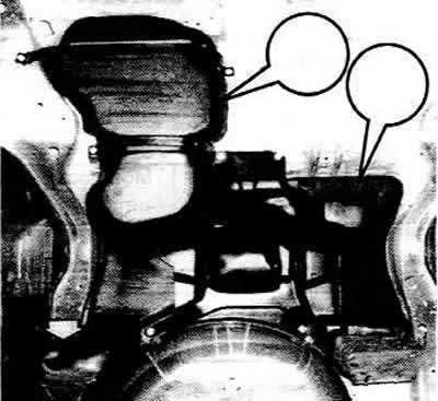
Fold back the trunk floor trim and remove the black metal cover (arrows).


Remove the multi-pin plug and the fuel return line, as well as the fuel supply line from the pump.

Now unscrew the fuel tank connecting flange. Usually a special key (2) is used for this.
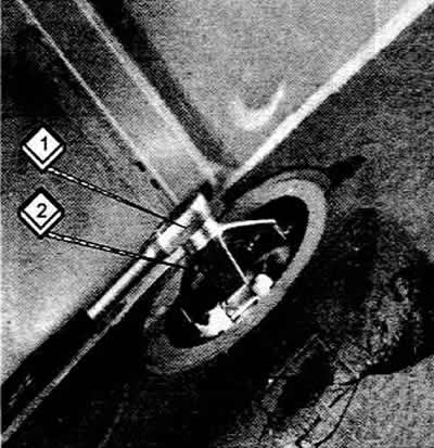
Now unscrew the fuel tank connecting flange. Usually a special key (2) is used for this.


The plastic union nut has small ribs through which you can insert a screwdriver (best of all is a blunt one). By lightly tapping the screwdriver, you can loosen the nut.


Now pull the connecting flange upwards.

Remove the return fuel line from the inside of the flange. Loosen the clamp and pull the fuel line down.

Remove the fuel tank sensor plug.
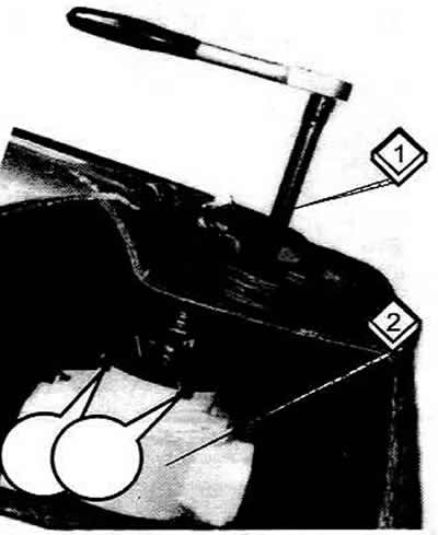
Remove the fuel tank sensor plug.


The above special device (1) is now inserted through the opening in the tank and into the inner part of the fuel intake housing (2). Now turn the inner part of the housing approximately 15° to the left, almost to the stop, to release the pump.
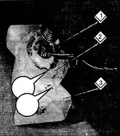
The above special device (1) is now inserted through the opening in the tank and into the inner…


Now you can lift the pump with the inner part outward together with the connecting flange. Before removing the pump, be sure to remember or mark the exact position of the pump installation, the method of connecting the hoses and wires, so that you can then install them in the same position. After making marks and disconnecting the fuel supply line, you can remove the pump from the inner part of the fuel intake housing. This operation depends on the diameter of the pump.


If the pump (1) has a diameter of 6 mm, turn the mesh at the bottom of the inner part of the housing (3) for fuel intake to the left and pull out the pump. When installing, push the protrusion (2) on the side of the pump into the groove. Do not forget about the gasket.

If the pump has a diameter of 4 mm, then squeeze the retaining clip on the upper side of the inner part of the fuel intake housing and pull out the pump. The pump can only be installed in one position.
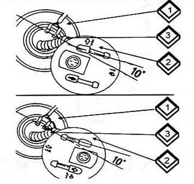
1 Fuel pump

1 Fuel pump
2 Connecting flange
3 Fuel hose


The pump is installed in the reverse order of removal. Pay attention to the relative position of the pump and the connecting flange, as well as the correct position of the sensor wire in the fuel tank.

For 2WD vehicles, install the connecting flange as shown on the right side of the figure and connect the hose as shown. The electrical wire for the fuel tank sensor must be routed between the fuel return line and the fuel tank.

For 4WD (Quattro) vehicles, the connection flange should be positioned as shown on the left side of the picture. The fuel tank sensor wire runs between the pump and the fuel tank.


Install the pump. The corresponding marks (arrows) must coincide with the large arrow on the outside (3).

Secure the inner part with the special key mentioned above.

When installing the connecting flange, pay attention to the installation position. The flange is marked with the symbols "QUATTRO" and "FRONT". "FRONT" in this case, it denotes models with a 2-wheel drive at the front. Both versions have an arrow that should match the arrow on the outside. Moisten the sealing ring of the connecting flange with gasoline before installation.
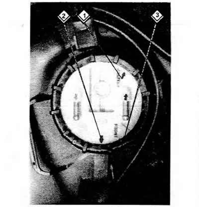
When installing the connecting flange, pay attention to the installation position. The flange is…


The original version of the article is posted on the website AUDImanual.ru
The article was checked by auto expert Georgy Rodionov
This article is available at russian, bulgarian, belarusian, ukrainian, serbian, croatian, romanian, polish, slovak, hungarian

Share information:
Previous articles
Audi 100 C4: Fuel system (gasoline)
Next articles

Fuel filter
Fuel tank sensor
Air filter
KE-Motronic injection system parts


Similar articles on other Audi car models:
Mechanical fuel pump — removal and installation Audi 80 B3 (1986-1991, petrol)
Control unit for Motronic, fuel pump relay, injectors... Audi A3 Type 8L (1996-2003)
Electric fuel pump Audi A4 B5 (1994-2001, petrol)
Fuel pump and fuel level sensor Audi A6 C4 (1994-1997)
Fuel pump / fuel level sensor Audi A8 D2 (1994-2002)
Electrical test of fuel pre-supply pump «G6» Audi Q5 Type 8R (2008-2017)
Fuel filter — replacement Audi A2 (1999-2005)
Link to this page in different formats


Visitor comments

No comments yet


How much will 24 + 40 =


100(C4, 1990-1994) 
  • General information
  • User manual
  • Power unit
  • Engine repair
  • Ignition system
  • Fuel system (gasoline)
  • Fuel system (diesel)
  • Lubrication system
  • Cooling system
  • Exhaust system
  • Transmission
  • Clutch
  • Car gearbox
  • Drive shafts
  • Chassis
  • Car suspension
  • Steering
  • Wheels and tires
  • Brake system
  • Body
  • Ventilation and heating
  • Body repair
  • Electrical equipment
  • Power devices
  • Lighting and appliances
  • Electrical circuits
 
100(C4, 1990-1994, petrol) 
  • General information
  • Operation and maintenance
  • Power unit
  • Engine repair
  • Exhaust system
  • Cooling system
  • Supply system
  • Air filter
  • Mono-Motronic injection system
  • Digifant injection system
  • KE-III-Jetronic and KE-Motronic
  • MPI and MPFI injection system
  • Transmission
  • Clutch
  • Car gearbox
  • Chassis
  • Suspension and steering
  • Brake system
  • Wheels and tires
  • Body
  • Exterior
  • Interior
  • Electrical equipment
  • Fuses and relays
  • Power devices
  • Ignition system
  • Lighting and signaling
  • Equipment and devices
  • Electrical circuits
 
100(C3, 1982-1990) 
  • General information
  • User manual
  • Maintenance
  • Specifications
  • Power unit
  • Engines 4-cylinder
  • Engines 5-cylinder
  • Diesel engine
  • Cooling system
  • Power system (carburetor)
  • Power system (injector)
  • Fuel system (diesel)
  • Transistor ignition system
  • Electronic ignition system
  • Transmission
  • Clutch
  • 4 speed gearbox 014
  • 5 speed gearbox 013 and 093
  • 5 speed gearbox 016 and 012
  • Shift mechanism KP 016
  • Automatic transmission
  • Front wheel drive
  • Chassis
  • Front suspension
  • Rear suspension
  • Steering
  • Brake system
  • Body
  • Body elements
  • Electrical equipment
  • Lighting and appliances
  • Power devices
  • Electrical circuits
 
100(C3, 1982-1990, petrol) 
  • General information
  • Maintenance and operation
  • 4 cylinder engine
  • Engine repair
  • Cooling and lubrication system
  • Supply system
  • Ignition system
  • 5 cylinder engine
  • Engine repair
  • Cooling and lubrication system
  • Supply system
  • Ignition system
  • Transmission
  • Clutch and drive shafts
  • 4 speed gearbox 014
  • 5 speed gearbox 013 and 093
  • 5 speed gearbox 016 and 012
  • Automatic gearbox
  • Chassis
  • Steering
  • Front suspension
  • Rear suspension
  • Brake system
  • Body
  • Body elements
  • Doors, locks and windows
  • Body repair
  • Electrical equipment
  • Equipment and devices
  • Power devices
  • Electrical circuits
 
100(C3, 1982-1990, diesel) 
  • General information
  • User manual
  • Maintenance
  • Troubleshooting
  • Power unit
  • Engine in a car
  • Engine removed
  • Cooling system
  • Fuel system
  • Exhaust system
  • Starting and charging
  • Preheating
  • Transmission
  • Clutch
  • Mechanical gearbox
  • Automatic gearbox
  • Drive shafts
  • Chassis
  • Brake system
  • Suspension
  • Steering
  • Body
  • Exterior
  • Interior
  • Electrical equipment
  • Equipment and devices
  • Electrical circuits
 
AudiManual.ru © 2017-2026 · Mobile version · Feedback · Sitemap: EN BG BY UA RS HR RO PL SK HU · Site search · News and articles
80 B2 · 80 B3 petrol · 80 B3 · 80 B4 · 100 C3 diesel · 100 C3 petrol · 100 C3 · 100 C4 petrol · 100 C4 · A3 Type 8L · A4 B5 petrol · A4 B5 · A4 B6 petrol · A4 B6 · A4 B7 · A4 B8 · A6 C4 · A6 C5 · A6 C5 Allroad · A8 D2 · Q5 Type 8R · Q7 Typ 4L · Audi A2 ·
This site uses cookies 🍪. Click the button to accept this fact.