
Table of contents: Disconnecting the injection system… ↓ Checking the connection to "mass" ↓ Checking the switch on the throttle… ↓ Adjusting the switch on the throttle… ↓ Checking the throttle positioner ↓ Checking the throttle potentiometer ↓ Throttle Potentiometer Contacts ↓ Injector check ↓ Checking the fuel cut-off while… ↓ Checking temperature sensors ↓ Checking fuel pressure ↓ Checking the damper ↓
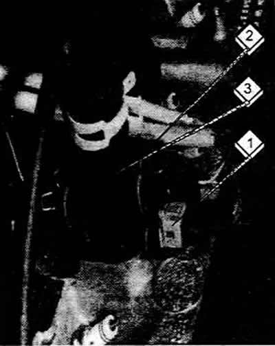
Disconnecting the injection system connector cover
Remove the cover over the waterproof housing in the engine compartment.
Press the locking clip and disconnect the plug.
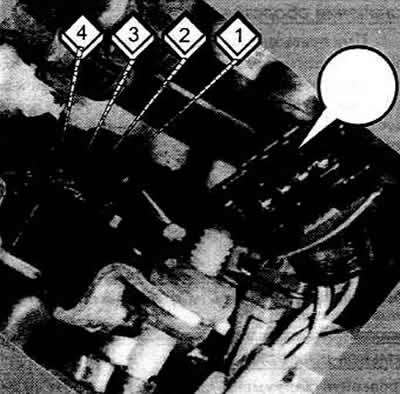
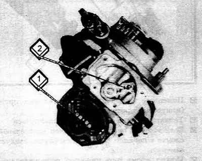
The plug (arrow) is disconnected from the switch on the throttle shaft. To facilitate troubleshooting, the contacts on the switch are numbered.
Press the plug until the locking clip snaps into place.
Checking the connection to "mass"
Before troubleshooting, you must ensure that the control unit ground connection is OK.
Disconnect the plug from the control unit.
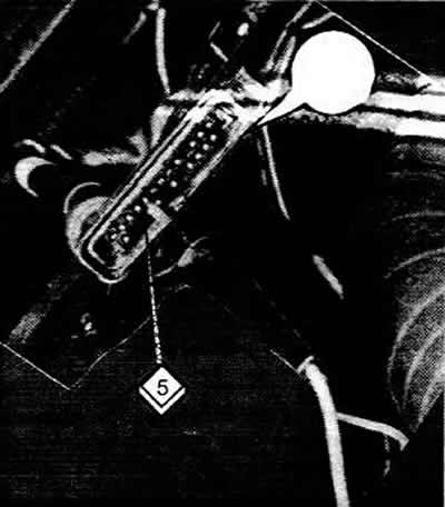
Connect the LED tester to the positive terminal of the battery and to contact 5 on the plug to ensure that there is a ground connection.
Perform a similar check on contact 25 of the plug.
If there is no connection to ground, check the wiring according to the electrical diagram and the ground connection point on the cylinder block.
Checking the switch on the throttle shaft and the control valve (distribution valve)
Electrical check
Turn on the ignition.
Open the throttle valve by hand using the drive lever and close it again.
The control valve should click twice.
If this happens, then the switch on the throttle shaft and the control valve are working properly
Checking the tightness of the control valve
Start the engine and let it idle.
Disconnect the plug on the control valve. The revs should increase as the ignition timing shifts to the "earlier" side.
Reconnect the plug, the speed should drop.
If so, the control valve is OK. Otherwise, it should be replaced.
Checking only the switch on the throttle shaft
The described test allows you to determine whether there is a fault in the switch on the throttle shaft or in the power supply to the valve.
Disconnect the plug on the control valve and connect the LED tester to the plug contacts.
Turn on the ignition, the LED should light up.
Open the throttle valve with your hand on the drive lever, the LED should go out.
If both happen, then the switch on the throttle shaft is OK.
Adjusting the switch on the throttle shaft
If the throttle positioner is replaced together with the switch, the switch stop screw must be readjusted.
Before starting adjustment, the throttle positioner plunger must be fully retracted.
To do this, apply a voltage of no more than 6 volts to both upper contacts of the positioner.
This can be done, for example, by using a 45-volt battery or by setting the charger to the 6-volt range.
Connect the wires, positive wire facing up.
Wait until the plunger has moved completely.
Connect an ohmmeter to both lower terminals of the throttle positioner.
Insert a 0.5mm thick feeler gauge between the plunger and the stop screw while observing the ohmmeter reading.
When the probe is inserted, the switch should be on and the ohmmeter reading should be Ohms.
Pull the probe out again. The switch should open contacts, the ohmmeter reading should be ∞ Ohm.
If necessary, turn the adjusting screw with a small Allen key and finally secure it with varnish.
Checking the throttle positioner
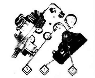
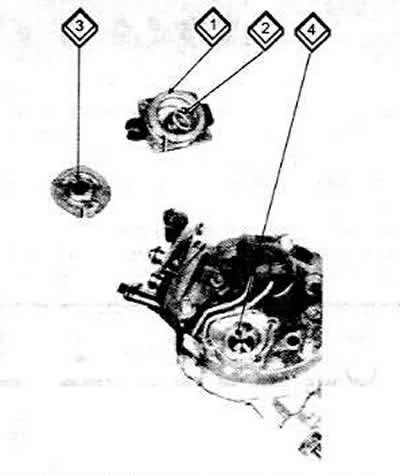
The throttle positioner (1) can be removed separately. This is necessary if the switch plunger (2) is defective. The throttle stop screw is marked with the number (3).
Disconnect the plug from the throttle positioner.
Set the charger to the 6-volt range and apply voltage to both top contacts of the positioner, positive pole on top.
The plunger should be fully retracted.
Change the polarity of the connecting wires (negative wire on top).
The plunger should extend fully.
If so, the throttle positioner is OK. Otherwise, it should be replaced.
You can also measure resistance.
The resistance of the positioner motor winding between both upper contacts should be 3-20 Ohm.
The resistance between both lower contacts with the throttle valve open should be Ohms.
With the throttle valve closed, the resistance should be infinite.
Checking the throttle potentiometer
Disconnect the plug from the throttle potentiometer.
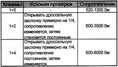
Connect the ohmmeter according to the table to two of the four contacts of the plug.
Throttle Potentiometer Contacts
If the specified values do not match the measured ones, then the throttle potentiometer is faulty.
The throttle potentiometer is factory adjusted and cannot be disassembled. Here it is removed so that the movable contact (2) and the conductive tracks (1) of the resistance are visible. If it is faulty, the injection system must be replaced.
Injector check
Check with the engine running: it must be warmed up to an oil temperature of at least 60°C. Remove the air intake pipe.
Start the engine and let it idle.
Observe the jet from the injector. It should be uniform and directed at the throttle valve.
To check the density, you should turn off the engine.
When the engine is not running, no more than two drops should come out per minute.
Further testing should be performed if the engine does not start.
Check the fuse.
Remove the air intake pipe.
Ask an assistant to turn the engine over with the starter.
The injector should spray fuel.
If not, the connector on the injection system at the top should be disconnected.
Connect an ohmmeter to the two middle contacts on the injection system.
At ambient temperature from +15°C to +30°C the resistance should be 1.2-1.6 Ohm, otherwise the injector is faulty. You should unscrew the bolt and replace the injector.
The voltage supply to the injector should be checked if, despite the correct resistance, it does not inject.
You should check the additional resistance of the injector; to do this, disconnect the additional resistance plug on the front right side of the rack.
Connect an ohmmeter to the plug contacts for resistance.
The measured value should be 3-4 Ohm. The LED tester should be connected (no other device!) to both middle contacts of the disconnected plug.
Turn on the starter, the LEDs should flash, otherwise there is a break in the wires or the control unit is faulty.
Checking the fuel cut-off while coasting
Remove the air intake pipe.
Start the engine, quickly accelerate above 300 rpm and sharply close the throttle valve. The clearly visible stream from the injector should briefly stop at this point. In this case, the fuel cut-off device when coasting is in order.
If this is not the case, the throttle shaft switch and the control unit should be checked.
Checking temperature sensors
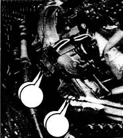
Intake air temperature sensor: Disconnect the brown plug at the top of the injection system.
Connect an ohmmeter to both outer contacts. Coolant temperature sensor: Disconnect the connector on the sensor at the bottom of the coolant pipe.
Connect an ohmmeter to both sensor contacts. The resistance value should be read for both sensors.
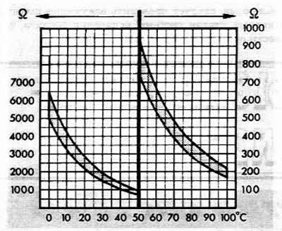
Using the graph below, check the resistance of the sensors to match the air or coolant temperature.
If the measured values correspond to those shown in the graph, then the sensors are OK.
Graph of the dependence of sensor resistance on the temperature of incoming air (left side) and coolant temperature (right side)
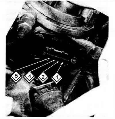
Temperature sensors
1 Heating of the intake pipe (red insulation)
2 Injection system (blue)
3 Coolant temperature indicators (black)
Checking fuel pressure
Fuel pressure can only be measured using a special device (in the workshop).
If incorrect fuel pressure is suspected, the pressure regulator should be disassembled.
To do this, you need to unscrew the four screws with a shaped head.
Check that the membrane is not damaged and that no dirt has gotten inside.
Disassembled pressure regulator
1 Lid
2 Spring
3 Membrane
4 Adjacent surface
Checking the damper
The damper may be damaged if the throttle valve closes suddenly when the gas pedal is released.
When adjusted correctly, the lever on the throttle shaft should push the damper pusher down 4-4.5 mm.
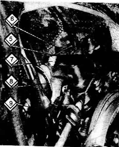
Damper adjustment
5. Flat measuring probe
6 Lever on the throttle shaft
7 Pusher
8 Damper
9 Lock nut on the adjusting screw
If this is not the case, the damper mounting nut should be loosened.
The damper should be screwed in until the pushrod and lever on the throttle shaft are in the correct position.
From this position, tighten the damper 4½ turns and tighten the nut again.
[Text provided by the online resource: AudiManual.ru]