
Table of contents: Checking the pressure regulator ↓ Checking the injectors ↓ Removal injectors ↓ Checking the coolant temperature… ↓ Checking the incoming air… ↓ Checking the air flow meter ↓ Measuring idle speed and CO content ↓
The work described can be performed with or without measuring instruments.
Checking the pressure regulator
To accurately measure the fuel pressure, a special VAG 1318 pressure gauge with additional parts is used, which allows you to measure the control values. The pressure at idle is 3.5 bar. If you remove the vacuum hose at the point shown by the arrow, the pressure will increase to 4.0 bar. After the engine stops, the pressure should be at least 3.0 bar. However, the pressure may drop to 2.5 bar after 10 minutes.
Checking the injectors
To check the injectors, check the voltage supply and the injectors themselves. A LED voltage tester is required.
Checking the voltage supply: For low power motors, remove the motor cover (large piece in the middle of the engine). To do this, turn the two quick-release connections a quarter turn to the left with a screwdriver, unhook the cover and remove it. For the remaining engines, remove the two fastening clamps on the right side of the trim, unhook the trim on the left side and remove the trim. First pull the casing above the injectors upwards by the rear edge, and then disengage it from the front.
Pull the plugs off the injectors. They are secured with wire fasteners.
Connect the LED voltage tester to the contacts of the removed plug. If you now turn the engine with the starter (assistant), the LED should blink. If this is not the case, then it can be assumed that the voltage supply is interrupted (the probe may also be faulty).
Checking the injectors: First, pull all the plugs off the injectors. Connect an ohmmeter to both contacts of the plug for injector #1. The resistance values should be 14-16 Ohms (low power engines), or 11-13 Ohm (other engines).
If the resistance values are as stated above, you can remove the injectors. They should be removed together with the fuel distributor pipe. Leave the plug connected to the injector and do not disconnect the fuel lines.
Place the injectors in 4 different measuring vessels and ask an assistant to turn on the starter. The cone-shaped stream of fuel coming out of the injectors should be the same for all injectors.
Turn off the ignition, remove all the plugs from the injectors and turn on the ignition again. Turn off the ignition again, and then turn it on for another 5 seconds. No more than 2 drops of fuel should come out of each injector. If so, the injectors are tight.
Removal injectors
Remove the engine casing (cover) as described earlier.
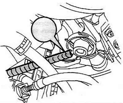
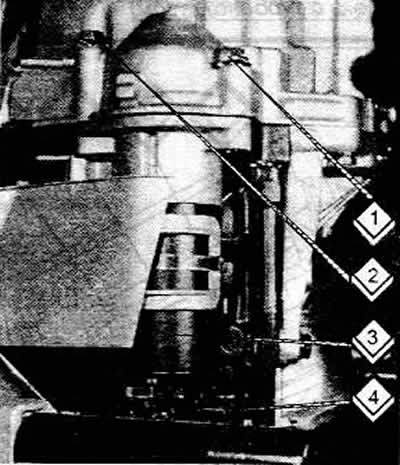
Remove the vacuum hose (3) from the fuel pressure regulator (1).
Remove the fuel tank cap for a while (to relieve pressure).
Cover the fuel line connection (2) with a thick cloth and very slowly loosen the connection using an open-end wrench (holding the other side of the connection). If fuel spills, it will be absorbed by the rag.
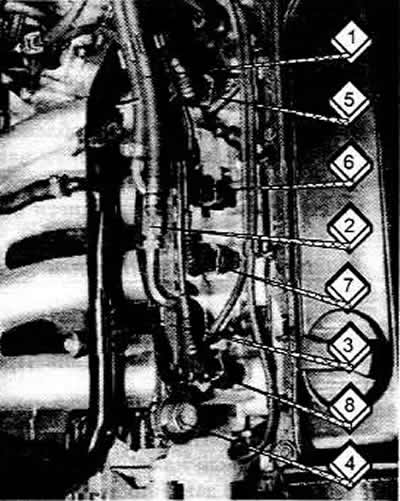
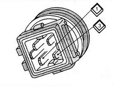
Disconnect the plugs from the injectors (4, 5, 6 and 7). At the same time, press down the wire fasteners on the back side.
For 1.8L engines, disconnect the plug from the Hall sensor.
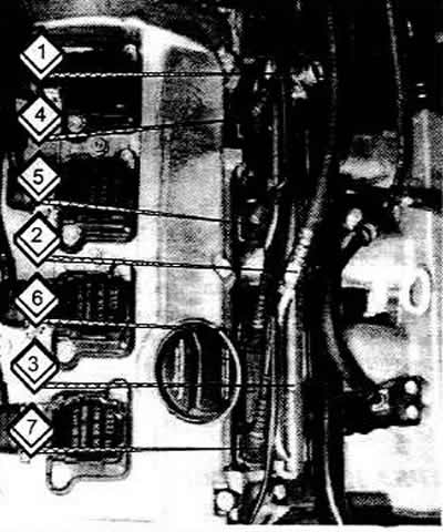
Unscrew the fuel distributor tube from the fuel line (2 bolts) and lift the distributor tube together with the injectors upwards. The figure shows the injectors with the already mentioned connections.
1 Return fuel line
7 Fuel supply line
3 Fuel distributor pipe
4 Fuel pressure regulator
5, 6, 7, 8 Injectors
To install the injector, remove the mounting bracket from the distributor tube and remove the injector from the tube.
Installation is carried out in the reverse order of removal, observing the following conditions:
Always replace the O-rings. Never remove the plastic cap from the injector to replace the front O-ring, it is pulled through the plastic cap. Lubricate the ring with clean engine oil.
Check that the mounting brackets are seated correctly.
Press the injectors vertically into the correct position on the distributor tube until they are fully seated and then secure them using the mounting brackets.
Install the fuel distributor tube with the installed injectors into the fuel rail and press evenly until it is seated correctly.
Screw in the bolts, slowly press the fuel distributor tube to the fuel line by hand and tighten the bolts to a torque of 1 Nm.
Checking the coolant temperature sensor
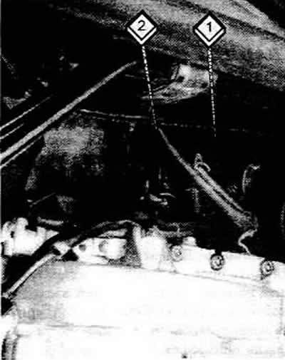
The sensor has a dual purpose. Firstly, it reports the engine coolant temperature and secondly, it connects to the remote thermometer on the instrument panel. The sensor (2) is located on the back of the cylinder head. If the air conditioning system is installed (1.8L engine). then the second temperature sensor (1) is located directly nearby.
To check, do the following:
- Remove the plug from the sensor in the coolant pipe on the back of the cylinder head.
- Connect the ohmmeter to the two contacts of the plug 1 and 3.
- With a cold engine and room temperature, the ohmmeter reading should be between 1.5 and 3 kOhm. If not, install a new sensor.
Checking the incoming air temperature sensor
The sensor is installed only on turbocharged engines. The sensor (2) is installed next to the throttle control unit (1).
Remove the plug from the sensor.
Connect an ohmmeter to both sensor contacts. With a cold engine and room temperature, the resistance should be 1.6-2.8 kOhm. Otherwise, replace the sensor.
Checking the air flow meter
Only the voltage supply to the air flow meter and the connection to the control unit can be checked if there is insufficient experience in electrical measurements. If the air flow meter does not pass the described tests, then further tests must be carried out in a workshop. The air flow meters on the "atmospheric" engine and on the turbocharged engine are different. On a non-turbocharged engine, the air flow meter is mounted on the air filter, on a turbocharged engine it is built into the air filter housing. A LED tester is required for testing.
Disconnect the plug from the air flow meter.
Connect the LED test leads between contact "3" of the plug and ground.
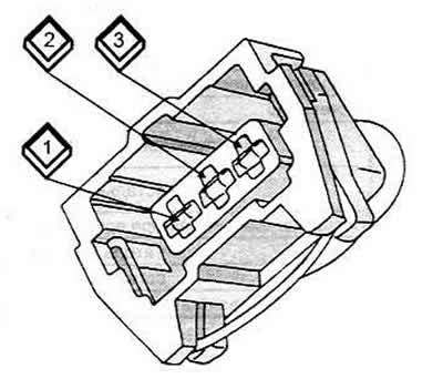
Air flow meter plug with 3 contacts (naturally aspirated engine)
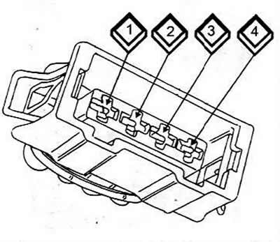
Air flow meter plug with 4 contacts (turbocharged engine)
The assistant must turn on the starter (the engine will start). If the LED lights up, then voltage is supplied to the flow meter.
To check the connections of the control unit, turn off the ignition and remove the plug from the unit. Now you need to check the flow of current.
On the plug for the engine without turbocharging, connect an ohmmeter between pin (1) on the plug of the control unit and contact (2) of the plug of the air flow meter. In addition, measure the resistance (9) and contact (2). In both cases, there should be conductivity (Ohm).
Measuring idle speed and CO content
Idle speed is adjusted automatically. When the engine is warm and the consumers are switched off, the speed is 820-90 rpm. The CO content in the exhaust gases cannot be measured by simple means, so you should contact a workshop for this.