
6-cylinder engines
Disconnect the wire from the negative battery terminal. Relieve the fuel pressure.
Remove the right and left support brackets, then the air intake duct.
Remove the engine compartment support bracket.
Remove the upper air cleaner mounting bolts and then the upper air cleaner.
Remove the lower air filter housing mounting bolts, then push the housing back and pull it out.
Remove the upper vent hose and then the right fuel line bracket.
Caution: When reassembling, install the new cable clamp in the same position as the original.
Remove the bolts securing the engine wiring harness clamp and secure the harness to the side.
Disconnect the plugs from the throttle valve potentiometer, temperature switch and idle speed control valve.
Remove the idle speed control valve, then disconnect the vacuum hoses going to the charcoal canister.
Remove the bolts securing the inlet air temperature sensor and place it aside.
Disconnect the air flow sensor connectors, then the connectors of the two knock sensors.
Disconnect the fuel return lines, then the pressure regulator vacuum hose.
Remove the fuel line mounting bolts, and then the fuel line assembly with the injectors.
When installing, use new O-rings and make sure the injectors are properly connected to the fuel line. Install them together with the line and tighten the bolts to 1 Nm.
Using new gaskets, connect the fuel supply and return pipes. Tighten the threaded connection to 26 Nm.
Connect all wires and vacuum hoses. Install the air filter housing, air ducts and properly secure the wires.
Install the support bracket. Start the engine and check for fuel leaks.
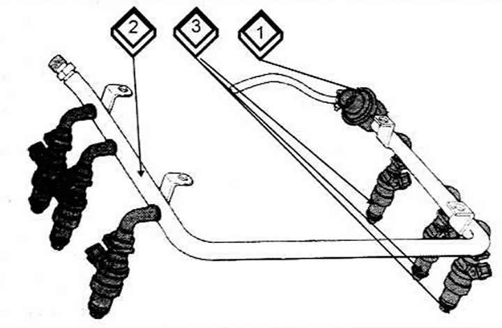
1 Pressure regulator
2 Ring pipeline
3 Fuel injector
[The full version is posted on the resource: Audimanual.ru]