Table of contents: Engines NC, 3D and 1T ↓ CN and DE engines ↓
Engines NC, 3D and 1T
Checking the serviceability of hydraulic tappets
Warning: After installing the hydraulic lifters, wait at least 30 minutes, then slowly rotate the crankshaft two full revolutions before starting the engine, otherwise the pistons may strike the valve heads. The lifter components need some time to settle into place.
1. Hydraulic tappets adjust valve clearance automatically and require no maintenance.
2. If the hydraulic tappets are too noisy, check their serviceability in the following way.
3. Start the engine and allow it to warm up to normal operating temperature. Increase the engine speed to 2500 rpm for approximately 2 minutes.
4. To determine which tappet is faulty, turn off the engine, then remove the camshaft cover (see Chapter 8).
5. Rotate the crankshaft with a wrench to turn the camshaft so that the working projection of the first cam of cylinder No.1 is directed upward.
6. Press the tappet with a wooden or plastic tool until you feel it touch the valve stem. Using a feeler gauge, measure the clearance between the base of the cam and the top of the valve tappet. If the clearance is more than 0.1 mm, the tappet is faulty and should be replaced.
7. Removal and installation of the pusher are described in Section 1B as part of the cylinder head rebuild procedure.
CN and DE engines
Checking and adjusting valve clearances
8. Valve clearances are adjusted by washers of different thickness installed in the tappet. The gaskets are made with a thickness of 3.00 to 4.25 mm with a step of 0.05 mm.
9. Adjust the clearances after installing a new camshaft or valves. The clearances should be rechecked after 1000 km, on a warm engine with a coolant temperature of 35°C.
10. Remove the valve cover.
11. Rotate the crankshaft with the cams for one cylinder in the highest position. Check the clearance between the cam and the tappet and record the measurements. Compare the obtained values with the data below: Engine Inlet Exhaust CN, DE 0.20-0.30 mm 0.40-0.50 mm
12. Repeat the action for all four cylinders. The valves are numbered from the toothed belt. Inlet valves - No.2-4-5-7-9, exhaust valves - No.1-3-6-8-10.
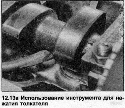
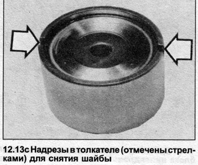
13. If any valve clearance exceeds the value given in the Specifications, remove the corresponding washer. Set the cylinder piston to TDC on the compression stroke, press the tappet so much that the adjusting washer can be removed from the tappet (see illustration). Each tappet has notches in the top frame that are made to facilitate washer removal (see illustration).
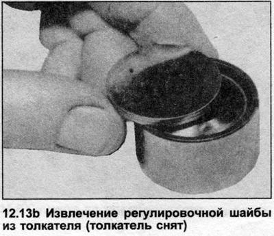
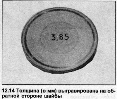
14. Note the thickness of the adjusting washer (engraved on the back side (see illustration), and calculate the thickness required to set the correct gap.
15. If the washers are not worn or damaged during removal, they can be reused.
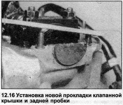
16. Install the valve cover with new gaskets (see illustration).