
Table of contents: Checking the clearance in the… ↓ Final installation of the crankshaft ↓
1. Installing the crankshaft is the first stage of the engine overhaul operation. It is assumed that the crankshaft, cylinder block and bearings are clean, checked, restored or replaced. If the oil injectors were removed, they must be installed and their mounting bolts tightened to the specified torque.
2. Place the cylinder block on a flat, clean workbench surface with the crankcase facing up. Wipe the bearing beds with a lint-free cloth - they must be spotlessly clean.
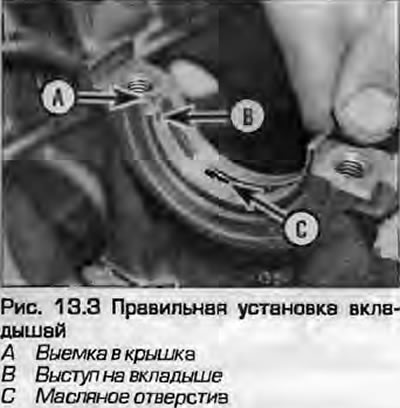
3. Wipe the backs of the liners clean and dry, leaving no lint from the rag. Place the liners in the bed, with the lock protrusion in the recess in the bed, correctly positioning the holes (Fig. 13.3). Do not use a hammer or other excessive force to install the liners; it is extremely important to keep the working surface of the liners undamaged and clean.
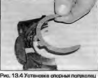
4. Install the thrust half rings on both sides of the third support. Lightly lubricate them with oil so that they hold. Install them with the projections in the block recesses, with the oil grooves facing outward (Fig. 13.4).
5. Wipe the crankshaft journals again with a clean rag. The oil passages must be free of dirt, which will damage the new bearings at the first start.
6. Carefully place the crankshaft into the crankcase, trying not to displace the liners.
Checking the clearance in the support bearings
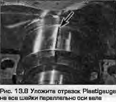
7. When installing the crankshaft, a gap must be left in its bearings to ensure oil circulation. This gap cannot be measured with a flat feeler gauge; a "Plastigauge" - a thin rod of soft plastic that is placed between the necks and liners when tightening the cap fasteners. Changing the width of the plastic rod serves to estimate the gap.
8. Small (slightly shorter than the width of the neck) place a piece of plastic on the neck parallel to the shaft axis (Fig. 13.8).
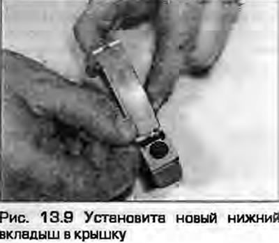
9. Wipe the surfaces of the new lower bearings and place them in the main bearing caps, aligning the locks with the recesses in the caps (Fig. 13.9).
10. Wipe the face of the liners and coat them with a thin layer of silicone grease to prevent the flattened plastic from sticking. Install the covers in their places, using the manufacturer's markings. The liner locks should be on one side.
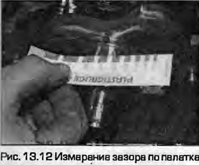
11. Starting from the center cap, tighten the mounting bolts half a turn to the specified torque Specifications for the first stage. Rotate the crankshaft at the same time to move the plastic. Gradually unscrew the bolts securing the covers and remove them, moving the plastic.
12. Apply the spatula supplied with the tool to the flattened rod "Plastigauge" - calculate the gap using it. Compare the results obtained with the data given in Specifications. If the clearance is outside the acceptable range, it may be due to dirt getting under the bearing. Try cleaning the components and re-measuring. If the results are still unacceptable, measure the journal diameters and check the bearing dimensions. If the piece of plastic is wider on one side than the other, the journal may be tapered and need to be re-ground.
13. If the results are satisfactory, carefully remove any remaining plastic from the bearings and journals. Use a soft scraper for this - a metal one may damage the surface.
Final installation of the crankshaft
14. Carefully remove the crankshaft from the block again. Wipe the bearing surfaces.
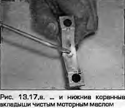
15. Lubricate the bearings with clean engine oil.

16. Place the crankshaft in the block with the connecting rod collar of the first cylinder facing up, so as to prepare for installing the first cylinder.
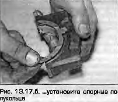
17. Make sure that the liners are correctly installed in the bearing caps, lubricate them with clean engine oil. Install the support half rings on both sides of the third bearing cap, with the protrusions in the recesses in the cap, and the oil channels facing outward (fig. 13.17, a, b).
 |
 |
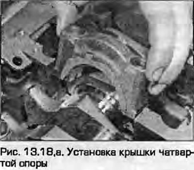
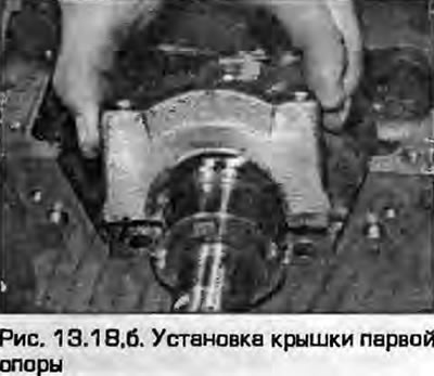
18. Install the bearing caps on the block, observing the order and orientation of the caps: cap No.1 should be on the timing belt side, the bearing locks should be installed on one side (fig. 13.18, a, b). Insert the cover mounting bolts and tighten them at this stage "by hand".
 |
 |
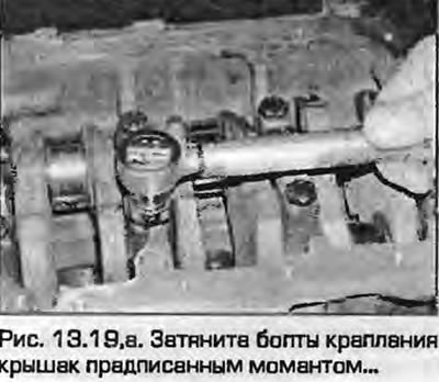
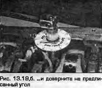
19. Starting from the middle support, tighten the cover mounting bolts to the specified torque and tighten to the specified angles Specifications (fig. 13.19, a, b).
 |
 |
20. Check the crankshaft rotation - it should be easy, without jamming. If force is required to rotate, find out the reason for it before continuing further assembly.
21. Check the crankshaft end clearance as described in paragraph 8. If the thrust surfaces are checked and new thrust half rings are installed, the clearance should be within "tolerances".
22. Install the pistons with the connecting rods, or attach them to the shaft as described in paragraph 15.
23. As described in the chapters 2A or 2B, do the following:
- a) Install the front and rear seal housings together with new seals.
- 6) Install the oil pump and oil receiver, deflector plate and pan.
- c) Install the flywheel and clutch or faceplate (what is provided).
- d) Install the crankshaft sprocket and timing belt.
[This publication is borrowed from the resource AUDIMANUAL]