
Valve mechanism
Image of the cylinder head. from the 2nd row (from the left).
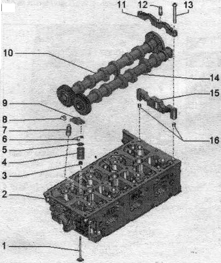
1. Valve: cannot be machined, only lapping is allowed; mark mont. reinstallation position.
2. Cylinder head: treat valve seats.
3. Valve stem seal: replace with cylinder head installed; replacement with the cylinder head removed.
4. Valve spring.
5. Valve spring plate.
6. Valve cracker.
7. Hydraulic compensator: fixed in the roller lever "pos. 9"; mark mont. reinstallation position; before installation, lubricate the working surfaces.
8. Locking clamp: not supplied separately; check the reliability of the fastening.
9. Rocker arm: mark mounting. reinstallation position; check the roller bearing for ease of movement; lubricate the working surfaces before installation; for installation, secure with the safety clamp "pos. 8" on the hydraulic compensator "pos. 7".
10. Intake camshaft; maximum runout: 0.01 mm.
11. Bearing cover: install in the proper position.
12. Clamp bracket support.
13. Bolt.
14. Exhaust camshaft; maximum runout: 0.01 mm.
15. Bearing bed: install in proper position.
16. Clamping sleeves: only for bearing seat behind camshaft thrust bearings.
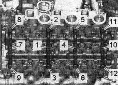
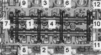
Bearing caps of cylinder bank 1 (right) - sequence and tightening torque of bolts
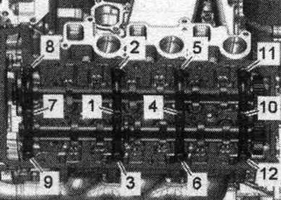
Tighten the bolts in 2 phases to the specified value. sequ..
| Step | Screws | Tightening torque |
| 1 | "1...12" | screw it in by hand until it stops |
| 2 | "1...12" | 9 Nm |
Bearing caps of cylinder bank 2 (left) - last, and tightening torque of bolts
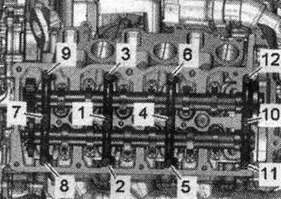
Tighten the bolts in 2 phases to the specified value. sequ..
| Step | Screws | Tightening torque |
| 1 | "1...12" | screw it in by hand until it stops |
| 2 | "1...12" | 9 Nm |
Removal camshafts, reinstalling used camshafts - cylinder bank 1 (right)
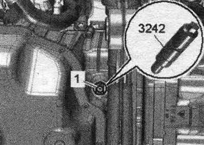
Remove the chain from the intake camshaft. Crankshaft "1" is fixed in the "TDC" position using locking screw "3242".
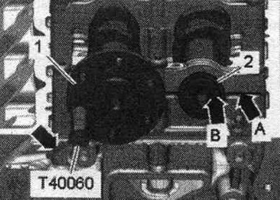
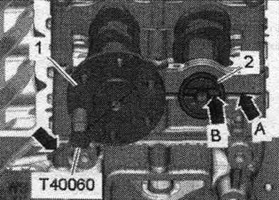
Check the camshaft position at the "TDC" mark. Intake camshaft "1" must be secured with pin "T40060." The pin "arrow" in the "T40060" alignment pin must be positioned parallel to the camshaft chain's axis of symmetry. The exhaust camshaft "2" must be in such a position that the groove "arrow B" is parallel above the joint "arrow A" between the bearing bed and the bearing cap.
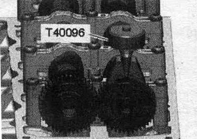
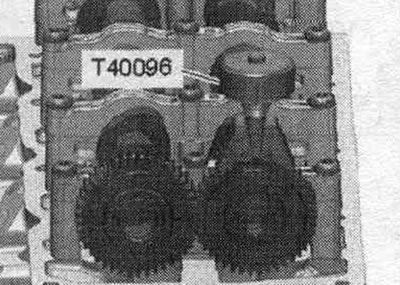
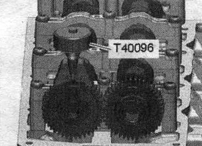
Install the T40096 camshaft tool onto the intake camshaft teeth so that each arm of the clamping tool fits into the corresponding half of the timing gear. The wide neck should fit into the wide half of the gear. Tighten the clamping device with the knurled wheel until the tooth profiles are level.
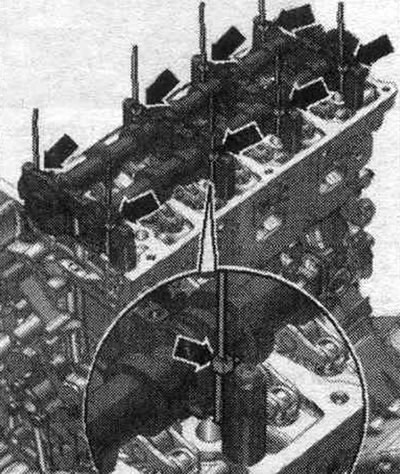
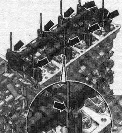
Wrap and tighten one "arrow" cable tie on the left and right around each bearing bed and cover. Using cable ties, you can remove the camshafts together with the bearings. This will prevent the parts from mixing.
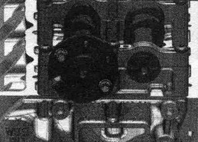
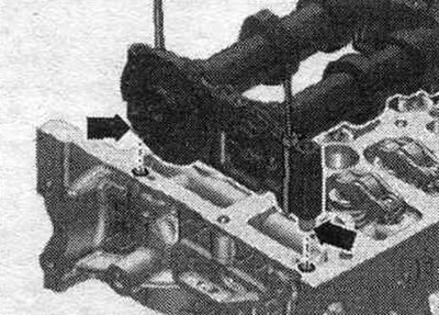
Remove the "T40060" dowel pin. Screw the two camshaft chain sprocket bolts into the threaded holes in the camshaft 5 turns, as shown in the figure.
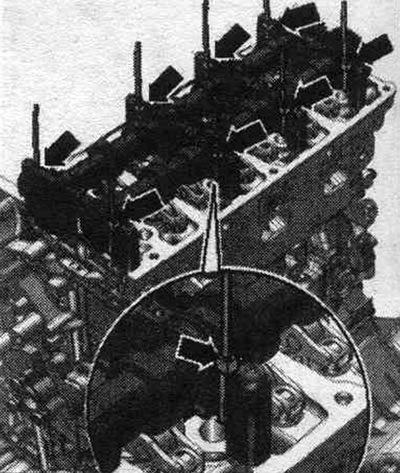
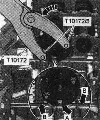
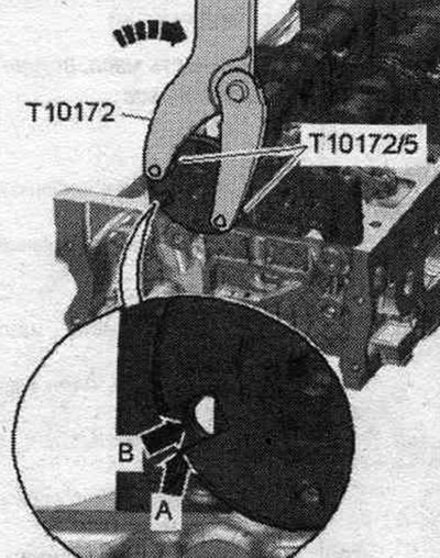
Install the "T10172" support with the "T10172/5" adapter onto both bolts and turn the camshafts approximately 30° counterclockwise "arrow" until the groove "arrow A" in the camshaft points vertically to the seal. "arrow B" surface of the cylinder head. Do not turn the camshafts further than indicated.
Loosen the bearing cap bolts in sequence. "12...1". When removing the camshafts, pay attention to the rocker arms and hydraulic compensators. Carefully remove the bearing caps from the camshafts. Do not mix components under any circumstances! Do not open cable ties until reinstallation.
Install
The crankshaft is secured with the "3242" locking bolt at the "TDC" position. Install the "T40096" camshaft adjusting tool onto the intake camshaft teeth so that each arm of the clamping tool engages the corresponding half of the gear. The wide neck should fit into the wide half of the gear. Tighten the clamping device with the knurled wheel until the tooth profiles are level.
Place the camshafts and camshaft bearings, secured with cable ties, onto the cylinder head. Cable ties prevent the camshafts and bearings from warping during tightening.
Check the camshaft position at the "TDC" mark. Intake camshaft "1" must be secured with pin "T40060." The pin "arrow" in the "T40060" alignment pin must be positioned parallel to the camshaft chain's axis of symmetry. The exhaust camshaft "2" must be in such a position that the groove "arrow A" is parallel above the joint "arrow B" between the bearing bed and the bearing cap.
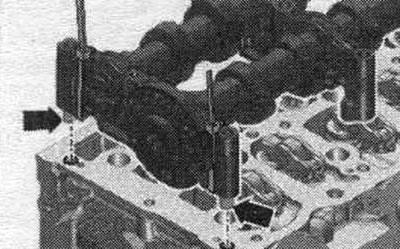
Remove the "T40060" dowel pin. Screw the two camshaft chain sprocket bolts into the threaded holes in the camshaft 5 turns, as shown in the figure. Install the support "T10172" with the adapter "110172/5" on both bolts and turn the camshafts approximately 30° counterclockwise "arrow" until the groove "arrow A" in the camshaft points vertically to the seal. "arrow B" surface of the cylinder head. Do not turn the camshafts further than indicated. Check the installation. position of the mounting bushings. Both "arrow" mounting bushings must be inserted into the holes in the bearing bed "IV." The mounting bushings must fit into the holes in the cylinder head.
Tighten the bearing cap bolts. Install the support "T10172" with the adapter "T10172/5" on both bolts and turn the camshafts approximately 30° clockwise "arrow" until the groove "arrow A" in the camshaft is located above the hole "arrow B" of the mounting pin "T40060".
Check the camshaft position at the "TDC" mark. Intake camshaft "1" must be secured with pin "T40060." The pin "arrow" in the "T40060" alignment pin must be positioned parallel to the camshaft chain's axis of symmetry. The exhaust camshaft "2" must be in such a position that the groove "arrow A" is parallel above the joint "arrow B" between the bearing bed and the bearing cap. Installation in reverse order. Remove the camshaft installation tool "T40096". Install the camshaft drive chains. Risk of damage to valves and piston crowns after working with the valve mechanism. Since the hydraulic lifters must be settled, after installing the camshafts the engine should not be run for approx. 30 min. To ensure that no valves come into contact with the cylinder head during operation, carefully crank the engine at least 2 revolutions.
Removal camshafts, reinstalling used camshafts - cylinder bank 2 (left)
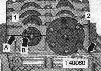
Remove the chain from the intake camshaft. Crankshaft "1" is secured at the "TDC" position using locking screw "3242." Check the camshaft position at the "TDC" mark. Intake camshaft "2" must be secured with pin "T40060." The pin "arrow" in the locating pin "T40060" must be positioned parallel to the camshaft chain's axis of symmetry. The exhaust camshaft "1" must be in such a position that the groove "arrow B" is parallel above the joint "arrow A" between the bearing bed and the bearing cap.
Install the T40096 camshaft tool onto the intake camshaft teeth so that each arm of the clamping tool fits into the corresponding half of the timing gear. The wide neck should fit into the wide half of the gear. Tighten the clamping device with the knurled wheel until the tooth profiles are level.
Wrap and tighten one "arrow" cable tie on the left and right around each bearing bed and cover. Using cable ties, you can remove the camshafts together with the bearings. This will prevent the parts from mixing.
Loosen the bearing cap bolts in sequence. "12...1". When removing the camshafts, pay attention to the rocker arms and hydraulic compensators. Carefully remove the bearing caps from the camshafts. Do not mix components under any circumstances! Do not open cable ties until reinstallation.
Install
The crankshaft is secured with the "3242" locking bolt at the "TDC" position. Install the "T40096" camshaft adjusting tool onto the intake camshaft teeth so that each arm of the clamping tool engages the corresponding half of the gear. The wide neck should fit into the wide half of the gear. Tighten the clamping device with the knurled wheel until the tooth profiles are level. Place the camshafts and camshaft bearings fixed with cable ties "arrows" on the cylinder head. Check the camshaft position at the "TDC" mark. The intake camshaft "2" must be locked with the pin "T40060". The finger "arrow" in the locating pin "T40060" must be parallel to the axis of symmetry of the camshaft chain drive. The exhaust camshaft "1" must be in such a position that the groove "arrow A" is parallel above the joint "arrow B" between the bearing bed and the bearing cap. Check the installation. position of the mounting bushings. Both "arrow" mounting bushings must be inserted into the holes in the bearing bed "IV." The mounting bushings must fit into the holes in the cylinder head.
Tighten the bearing cap bolts. Check the camshaft position at the "TDC" mark. Intake camshaft "2" must be secured with pin "T40060." The pin "arrow" in the "T40060" alignment pin must be positioned parallel to the camshaft chain's axis of symmetry. The exhaust camshaft "1" must be in such a position that the groove "arrow A" is parallel above the joint "arrow B" between the bearing bed and the bearing cap. Installation in reverse order. Remove the camshaft installation tool "T40096". Install the camshaft drive chains. Risk of damage to valves and piston crowns after working with the valve mechanism. Since the hydraulic lifters must be settled, after installing the camshafts the engine should not be run for approx. 30 min. To ensure that no valves come into contact with the cylinder head during operation, carefully crank the engine at least 2 revolutions.