
Table of contents: Removal ↓ Installation ↓
Removal
1. Set the gear shift lever to neutral position.
2. Remove the seal from the fairing (see arrows in the illustration), and then remove the grille 1 of the fairing.
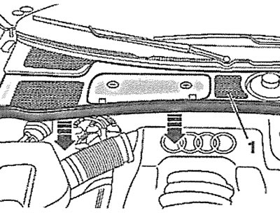
8.2 Remove the seal from the fairing (see arrows), and then remove the fairing grille
Attention! If the radio has an access code, then when the battery is disconnected, it is erased, so check and write down this code. Otherwise, the radio can only be turned on by asking a representative of the manufacturer.
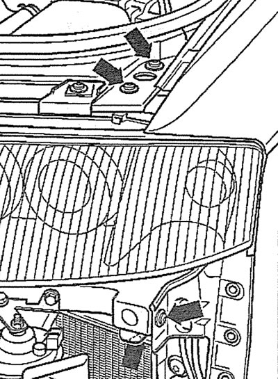
3. Disconnect the ground (-) wire terminal from the negative battery terminal by unscrewing the nut (see arrow in illustration).
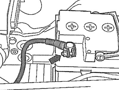
8.3. Disconnect the ground (-) wire terminal from the negative battery terminal by unscrewing the nut (see arrow)
Attention! The manufacturer recommends draining the refrigerant from the air conditioner. However, you cannot open the refrigerant circulation system yourself - there is a risk of frostbite! You can try to disconnect the air conditioner compressor without opening the system and without disconnecting the hoses and pipes from it, and move it away from the work site.
4. Remove the cap from the coolant expansion tank.
Caution: Before removing the expansion tank cap, place a rag on it to avoid being burned by hot coolant or steam.
5. Remove the front wheels.
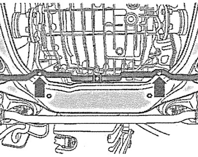
6. Cars with parking heater. Unscrew the bolts (see arrows in the illustration) fastening the heater pipe to the soundproofing shield.
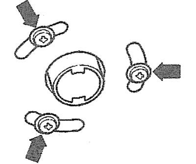
8.6. Unscrew the bolts (see arrows) fastening the heater pipe to the soundproofing shield. Cars with a parking heater
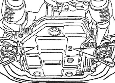
7. Unscrew bolts/remove fasteners 1-3 and remove the engine splash guard (see illustration).
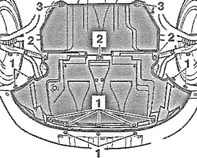
8.7. Unscrew bolts/remove fasteners 1-3 and remove engine splash guard
8. Unscrew the bolts (see arrows in the illustration) engine splash guard bracket and remove the bracket.
8.8. Unscrew the bolts (see arrows) engine splash guard bracket and remove the bracket
9. Remove the front bumper (see the relevant chapter).
10. Disconnect the plug (see arrow in illustration) sound signal.
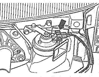
8.10. Disconnect the plug (see arrow) sound signal
11. Remove the left fairing (see arrow in illustration 8.11) and the right fairing (see arrow in illustration 8.11a) additional radiator.
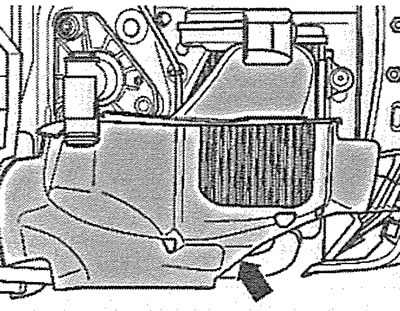
8.11 Remove the left fairing (see arrow) additional radiator |
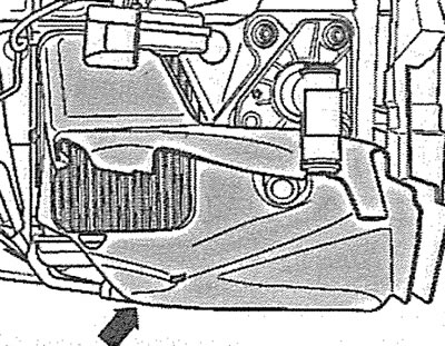
8.11a. Remove the right fairing (see arrow) additional radiator |
12. Place a suitable container under the engine to collect the coolant.
13. Unscrew the plug (see arrow in illustration) drain hole on the thermostat housing and drain the coolant.
8.13. Unscrew the plug (see arrow) drain hole on the thermostat housing and drain the coolant
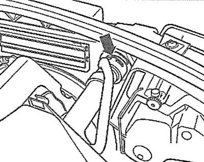
14. Disconnect the lower hose from the radiator (see arrow in illustration) and drain the coolant from the radiator.
8.14. Disconnect the lower hose from the radiator (see arrow) and drain the coolant from the radiator
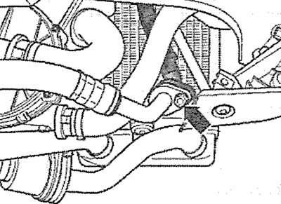
15. Place a suitable container to collect the transmission oil and disconnect the transmission oil circulation hose from the radiator frame (see arrow in illustration).
8.15. Disconnect the transmission oil circulation hose from the radiator frame (see arrow)
16. Disconnect the hose from the transmission oil cooling radiator (see arrow in illustration).
17. Remove the cap from the power steering expansion tank (see arrow in illustration).
8.17. Remove the cap from the power steering expansion tank (see arrow)
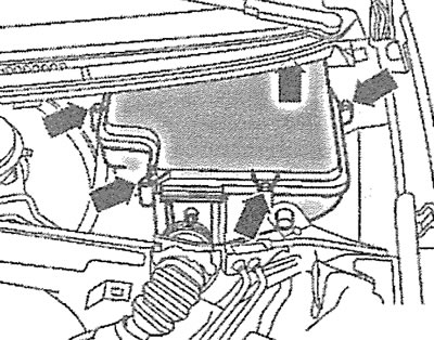
18. Press the latches and remove the air filter cover 2 (see illustration).
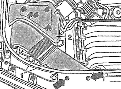
8.18. Press the fasteners and remove the air filter cover 2
19. Unscrew the bolts (see arrows in illustration 8.18) fastening the air intake 1 to the upper front cross member and remove the air intake.
20. Disconnect the headlight power connectors on both sides (see arrow in illustration).
8.20. Disconnect the headlight power connectors on both sides (see arrow)
21. Release plugs 1 and 2 from the holders and move the wiring harness away from the work area (see illustration).
8.21. Release plugs 1 and 2 from the holders and move the wiring harness away from the work area
22. Disconnect the plug (see arrow in illustration) radiator fan, release the wire harness from the holder.
8.22. Disconnect the plug (see arrow) radiator blower fan
23. Remove the hood release cable.
24. Disconnect the upper hose from the radiator (see arrow in illustration).
8.24. Disconnect the upper hose from the radiator (see arrow)
25. Unscrew the bolts (see arrows in the illustration), press the fasteners and remove the left and right radiator fairings.
8.25. Unscrew the bolts (see arrows), press the clamps and remove the left and right radiator fairings
26. Disconnect the outside air temperature sensor 1 and release the wire from the holder (see illustration).
8.26. Disconnect the outside air temperature sensor 1 and release the wire from the holder
27. Unscrew the bolts (see arrows in illustration 8.26) power steering line holders and move the line away from the work area without opening the system. Carefully tie up the line to avoid damaging it.
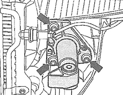
28. Unscrew the holder bolts (see arrows in the illustration) and disconnect the refrigerant circulation lines from the air conditioner compressor.
8.28. Unscrew the holder bolts (see arrows) and disconnect the refrigerant circulation lines from the air conditioner compressor
Attention! All work related to the air conditioner should be entrusted to a specialized workshop. Do not open the refrigerant circulation system yourself - there is a risk of frostbite.
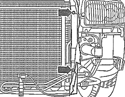
29. Unscrew the bolts (see arrows in the illustration) on the right and left sides of the upper front cross member.
8.29. Unscrew the bolts (see arrows) on the right and left sides of the upper front cross member
30. Unscrew the shock absorber mounting bolts (see arrows in the illustration) and carefully remove the radiator frame, working together with an assistant.
8.30. Unscrew the shock absorber mounting bolts (see arrows) and carefully remove the radiator frame, working together with an assistant
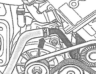
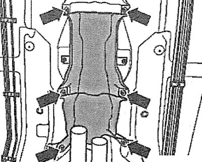
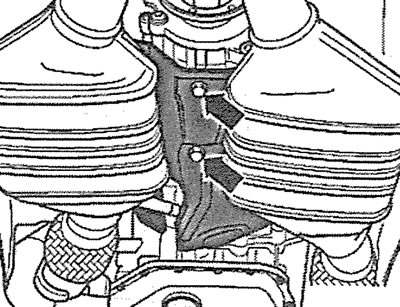
31. Remove the engine protective covers (see arrows in the illustration).
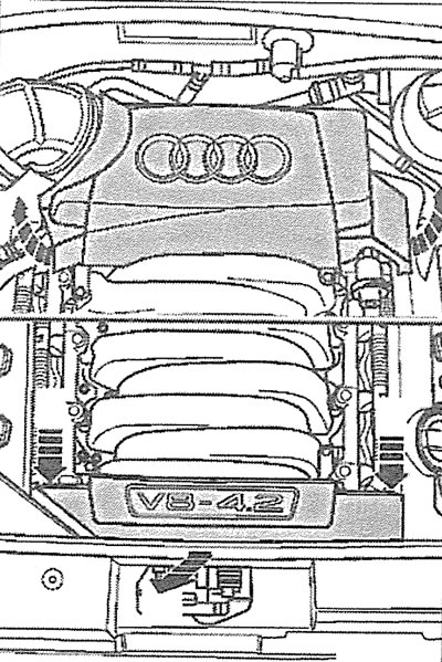
8.31 Remove the engine protective covers (see arrows)
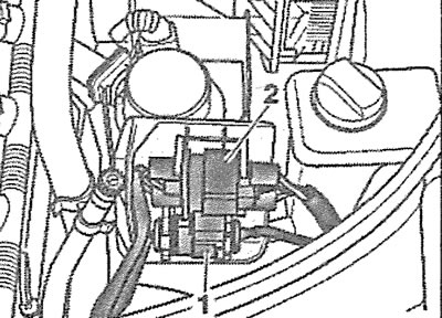
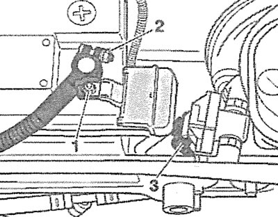
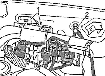
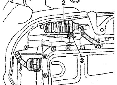
32. Disconnect the coolant hoses from expansion tank 2 by removing clamps 1 and 3 (see illustration).
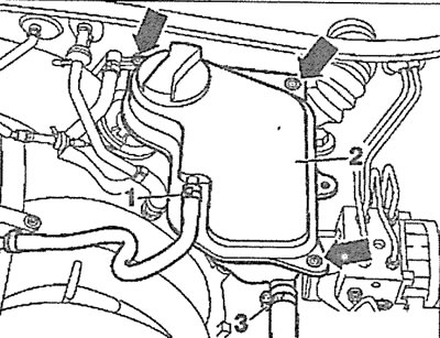
8.32. Disconnect the coolant hoses from expansion tank 2 by removing clamps 1 and 3
33. Unscrew the mounting bolts (see arrows in illustration 8.32) and remove the coolant expansion tank 2.
34. Disconnect the low pressure hoses (see arrows in the illustration).
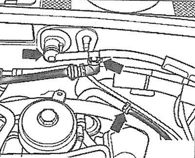
8.34. Disconnect the low pressure hoses (see arrows)
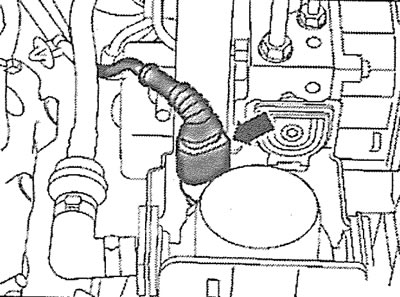
35. Disconnect the coolant hose by removing the clamp (see arrow in illustration).
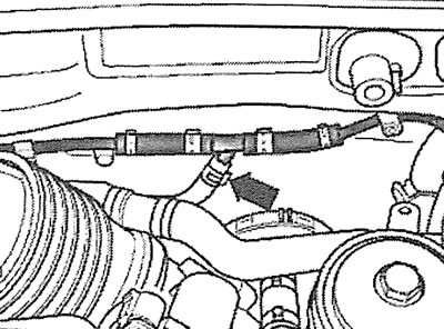
8.35. Disconnect the coolant hose by removing the clamp (see arrow)
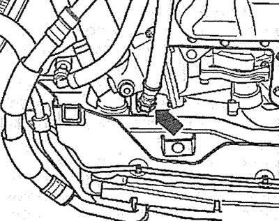
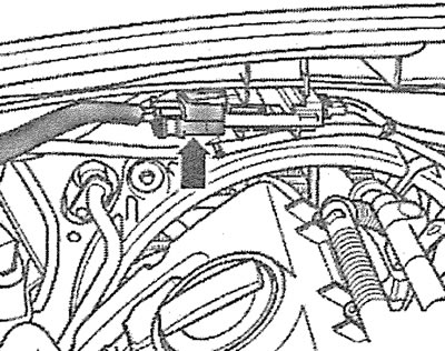
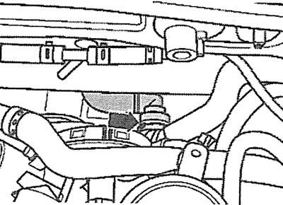
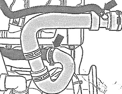
36. Disconnect the low pressure hose from the intake manifold (see arrow in illustration).
8.36. Disconnect the low pressure hose from the intake manifold (see arrow)
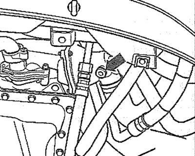
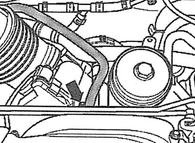
37. Disconnect the coolant hose from the engine (see arrow in illustration).
8.37. Disconnect the coolant hose from the engine (see arrow)
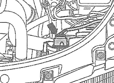
38. Disconnect the plug (see arrow in illustration) from the brake booster and release the wire from the holder.
8.38. Disconnect the plug (see arrow) from the brake booster
39. Pump out the fluid from the power steering reservoir using an oil pumping tool, part number VAG 1358A or VAG 1782A. Collect the leaking fluid with a rag.
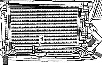
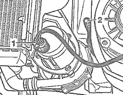
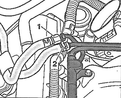
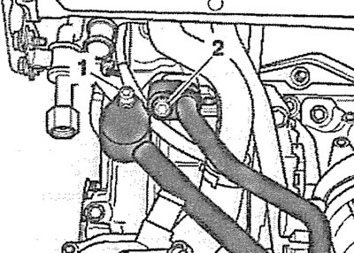
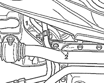
40. Disconnect the hose from the power steering reservoir by removing clamp 1 (see illustration).
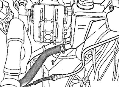
8.40. Disconnect the hose from the power steering reservoir by removing clamp 1
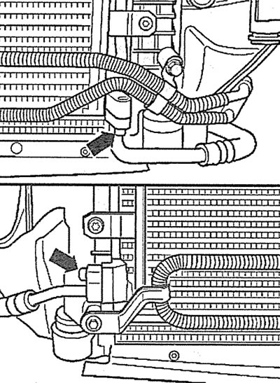
41. Disconnect the coolant hoses by removing the mounting clamps (see arrows in the illustration).
8.41. Disconnect the coolant hoses by removing the mounting clamps (see arrows)
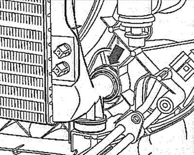
42. Disconnect the coolant hose (see arrow in illustration) from the oil radiator.
8.42. Disconnect the coolant hose (see arrow) from the oil radiator
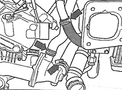
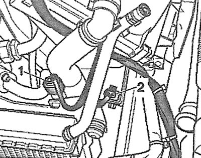
43. Disconnect the coolant hoses by removing the mounting clamps (see arrows in the illustration).
S.43. Disconnect the coolant hoses by removing the mounting clamps (see arrows)
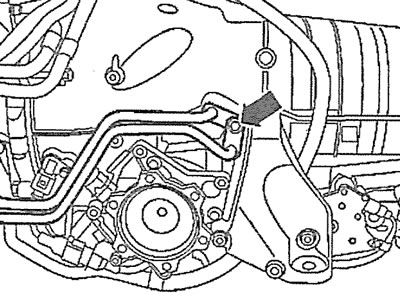
44. Vehicles with afterburning system. Disconnect plug 1 from the electric motor of the fresh air supply pump to the outlet valves and release the wire from the holder (see illustration).
8.44. Disconnect plug 1 from the electric motor of the fresh air supply pump to the outlet valves and release the wire from the holder. Vehicles with an afterburning system
45. Disconnect wire 2 "ground" (-) from the side member (see illustration 8.44).
46. Disconnect plugs 1 and 2 located in front of the air filter (see illustration).
8.46. Disconnect plugs 1 and 2 located in front of the air filter
47. Release plug 3 of the solenoid valve of the adsorber from the holder 2 (see illustration), then remove the valve.
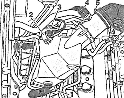
8.47. Release plug 3 of the adsorber solenoid valve from holder 2
48. Disconnect plug 4 of the mass air flow sensor (see illustration 8.47).
49. Disconnect hose 1 of the fresh air supply pump to the outlet valves (see illustration 8.47).
50. Remove clamp 5 and disconnect the supply air duct from the air filter housing (see illustration 8.47).
51. Unscrew the bolt (see arrow in illustration 8.47) fasteners and remove the air filter housing together with the mass air flow sensor.
52. Remove the clamp (see arrow in illustration) fasteners and disconnect the supply air duct from the throttle valve.
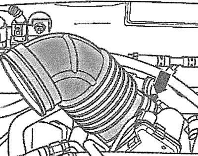
8.52. Remove the clamp (see arrow) using the fasteners, disconnect the supply air duct from the throttle valve
53. Disconnect the supply 1 and return 2 fuel lines (see illustration).
8.53. Disconnect the supply 1 and return 2 fuel lines
Caution! The fuel system is under pressure. Before disconnecting the fuel lines, cover the joint with a rag. Disconnect the fuel line slowly to relieve pressure in the system.
54. Cars with afterburning system. Remove the mounting clamp (see arrow in illustration) and disconnect the hose from the fresh air supply valve to the outlet valves.
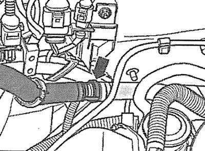
8.54 Remove the mounting clamp (see arrow) and disconnect the hose from the fresh air supply valve to the outlet valves
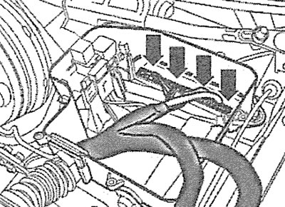
55. Disconnect plugs 1-4 located on the engine compartment bulkhead (see illustration) and move the wiring harness away from the work area.
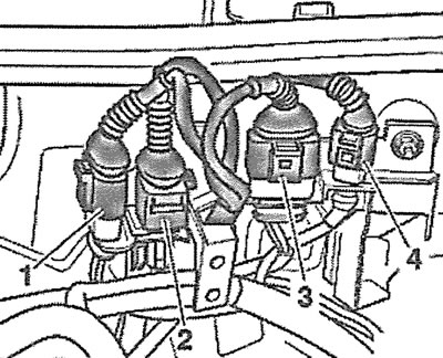
8.55. Disconnect plugs 1-4 located on the engine compartment bulkhead
56. Disconnect the positive potential (+) cable terminal from the battery by unscrewing nuts 1 and 2 (see illustration).
8.56. Disconnect the positive potential (+) cable terminal from the battery by unscrewing nuts 1 and 2
57. Disconnect plug 3 of the brake booster sensor (see illustration 8.56) and release the sensor wire from the holder.
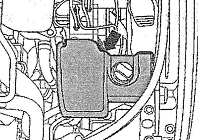
58. Unscrew the bolts (see arrows in the illustration) and remove the engine control unit cover.
8.58. Unscrew the bolts (see arrows) and remove the engine control unit cover
59. Use a screwdriver to pry up the mounting bracket (see arrow in illustration) and remove the engine control unit without disconnecting the wiring harness from it.
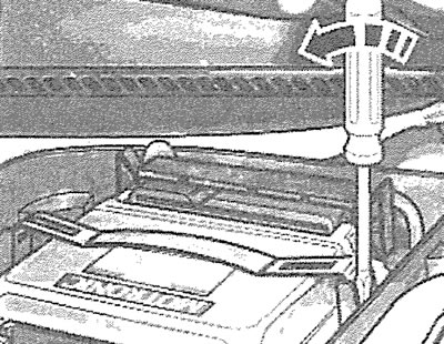
8.59. Use a screwdriver to pry up the mounting bracket (see arrow) and remove the engine control unit without disconnecting the wiring harness from it
60. Disconnect the plugs (see arrows in the illustration) engine control unit.
8.60. Disconnect the plugs (see arrows) engine control unit
61. Use a screwdriver to pry up the retainer (see arrow in illustration) and remove the fuse and relay box.
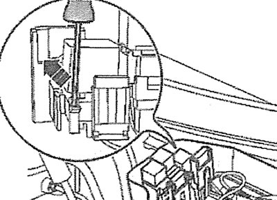
8.61. Use a screwdriver to pry up the retainer (see arrow) and remove the fuse and relay box
62. Disconnect the wiring harness from the engine control unit.
63. Disconnect the ground (-) wire by unscrewing nut 2 (see illustration).
8.63. Disconnect the ground (-) wire by unscrewing nut 2
64. Release the wiring harness from the holder, then unscrew the bolts 1 and remove the holder (see illustration 8.63).
65. Unscrew bolts 1 and 2 of the holders and disconnect the exhaust pipes (see illustration).
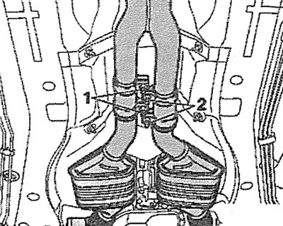
8.65. Unscrew bolts 1 and 2 of the holders and disconnect the exhaust pipes
66. Unscrew the bolts (see arrows in the illustration) and remove both heat shields.
8.66. Unscrew the bolts (see arrows) and remove both heat shields
67. Unscrew the bolts (see arrows in the illustration) and remove the heat shield A of the propeller shaft.
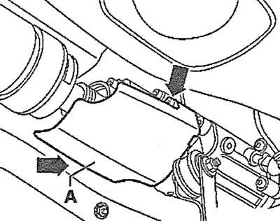
8.67. Unscrew the bolts (see arrows) and remove the heat shield A of the propeller shaft
68. Loosen the mounting bolts and carefully move the propeller shaft toward the gearbox flange. Tie the shaft to the body with wire.
69. Unscrew the bolts (see arrows in the illustration) and remove the gearbox heat shield.
8.69. Unscrew the bolts (see arrows) and remove the gearbox heat shield
70. Unscrew the bolt (see arrow in illustration) fastenings of the left inlet pipe trim.
8.70. Unscrew 6 bolts (see arrow) left inlet pipe lining fastenings
71. Unscrew bolts 1, 3 and 4 and remove the heat deflector shield together with the exhaust system bracket (see illustration).
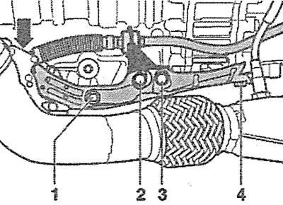
8.71. Unscrew bolts 1, 3 and 4 and remove the heat deflector shield together with the exhaust system bracket
72. Unscrew bolt 2 of the gear selection cable end holder (see illustration 8.71).
73. Disconnect the ball joint of the gear selection cable end (see arrow in illustration 8.71) from the gearshift lever on the gearbox.
74. Unscrew bolts 1 and 2 securing the left and right gearbox suspension supports (see illustration).
8.74. Unscrew bolts 1 and 2 securing the left and right gearbox suspension supports
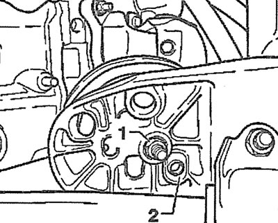
75. Turn the lock 1 and disconnect the gearbox wiring harness plug (see illustration).
8.75. Turn the lock 1 and disconnect the gearbox wiring harness plug
76. Disconnect plug 2 of the multifunction switch of the gearbox, remove the holder 3 of the plug (see illustration 8.75).
77. Remove heat shields 1 from both drive shafts (see illustration).
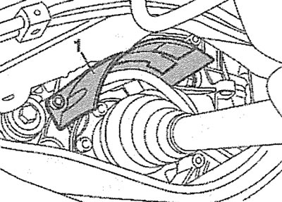
8.77. Remove heat shields 1 from both drive shafts
78. Disconnect both drive shafts from the gearbox, then move and tie up the right drive shaft and remove the left drive shaft (see the relevant chapter).
8.78. Unscrew bolts 1 and 2 and disconnect the refrigerant circulation pipes from the air conditioner compressor
79. Unscrew bolts 1 and 2 and disconnect the refrigerant circulation pipes from the air conditioning compressor (see illustration).
Attention! All work related to the air conditioner must be entrusted to a specialized workshop. Do not open the refrigerant circulation system yourself - risk of frostbite!
80. Remove the clamp (see arrow in illustration) fastenings of the refrigerant circulation pipeline.
8.80 Remove the clamp (see arrow) refrigerant circulation pipeline fastenings
81. Unscrew the bolt (see arrow in illustration) fasteners and remove the refrigerant circulation pipe.
8.81. Unscrew the bolt (see arrow) fasteners and remove the refrigerant circulation pipe
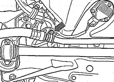
82. Disconnect the power steering pressure hose by unscrewing the union nut (see arrow in illustration). Collect the leaking liquid with a rag.

8.82. Disconnect the power steering pressure line by unscrewing the union nut (see arrow)
83. Disconnect the pressure line from the power steering pump(see arrow in illustration).
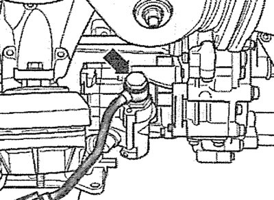
8.83. Disconnect the pressure line from the power steering pump (see arrow)
84. Unscrew nuts 1-4 of the anti-roll bar mounting cushions (see illustration).
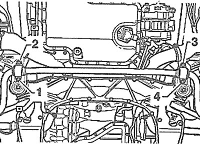
8.84. Unscrew nuts 1-4 of the anti-roll bar mounting cushions
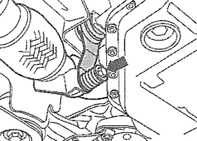
85. Cars with automatic transmission. Unscrew the bolt (see arrow in illustration) transmission oil circulation pipe holder and disconnect the pipes. Collect the leaking oil with a rag.
8.85. Unscrew the bolt (see arrow in illustration) transmission oil circulation line holder and disconnect the lines. Cars with automatic transmission
86. Cars with automatic transmission. Disconnect the pipe from the transmission oil cooling radiator (see arrow in illustration).
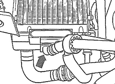
8.86. Disconnect the pipe from the transmission oil cooling radiator (see arrow). Cars with automatic transmission
87. Cars with automatic transmission. Unscrew bolts 1 and 2 of the transmission oil circulation pipeline mounting bracket, remove the bracket, and then carefully remove the pipelines (see illustration).
8.87. Unscrew bolts 1 and 2 of the transmission oil circulation pipeline mounting bracket, remove the bracket, and then carefully remove the pipelines. Cars with automatic transmission
88. Unscrew the lower nuts 1 of the right and left engine mounts (see illustration), loosen the upper nut securing the left engine mount support.
8.88. Unscrew the lower nuts 1 of the right and left engine mounts
89. Unload the power unit supports by lifting the engine and gearbox using a lift or hoist. In specialized workshops, a VAS 6100 service crane and jack 1, which are installed under the gearbox, are used for this purpose (see illustration).
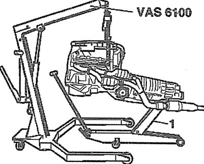
8.89. Unload the power unit supports by lifting the engine and gearbox with the VAS 6100 service crane. Jack 1 is installed under the gearbox
Caution: Do not place a support or jack under the oil pan.
90. First unscrew the lower and then the upper bolts securing the gearbox to the engine.
91. Cars with automatic transmission. Disconnect the torque converter from the drive disk, to which it is attached with three bolts. The bolts are unscrewed alternately through the mounting hole for the starter (see illustration), therefore, the starter must first be removed (see the relevant chapter). To ensure that the bolts enter the starter mounting hole, turn the engine to the right using a socket head on the bolt on the crankshaft.
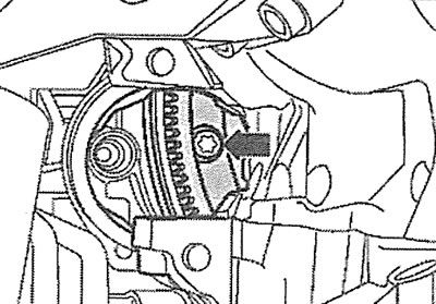
8.91. Unscrew the bolts securing the starter to the drive disk, alternately leading the bolts into the hole for the starter (see arrow). Cars with automatic transmission
92. Carefully separate the engine and gearbox, making sure not to let the torque converter fall out. Then remove the engine from the engine compartment.
Installation
The engine is installed in the reverse order of removal.
93. Tighten the gearbox to engine mounting bolts in the sequence shown in the illustration:
- 1 - bolt M10x80. Tightening torque - 65 Nm (if the bolt does not have a ribbed head), 85 Nm (if the bolt has a ribbed head);
- 2, 4, 5-bolt M12x105. Tightening torque-65 Nm;
- 3-bolt M12x110. Tightening torque-65 Nm;
- 6-bolt M12x120. Tightening torque-65 Nm;
- 7-bolt M12x170. Tightening torque-65 Nm;
- 8-10 - bolt M10x60. Tightening torque - 45 Nm.
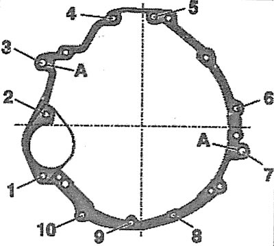
8.93. Tighten the gearbox mounting bolts to the engine in the following sequence: A - centering bushings
A link to the original source is available on the website Audimanual.ru