
Recommendations for engine removal
Before you begin, please read the entire engine removal section carefully.
If the engine is removed for repair, it is necessary to select a place for the work, provide space for maintenance and storage of spare parts. It is recommended to carry out repairs at a service station or in a garage with a level horizontal floor with a clean hard surface.
Before removing, clean and wash the engine and engine compartment. To remove the engine, use a lifting mechanism that allows you to safely lift the power unit.
If you are removing the engine for the first time, you should invite an experienced specialist. Some work should be done with an assistant.
All clamps and clips that are damaged or cut during engine removal must be replaced with new ones during engine assembly.
The engine is removed forward without the gearbox.
The drained coolant must be collected and disposed of.
Before disconnecting the battery, find out if you have a radio activation code.
Removal
The battery is located under the luggage compartment floor.
Turn off the ignition and disconnect the ground wire from the battery.
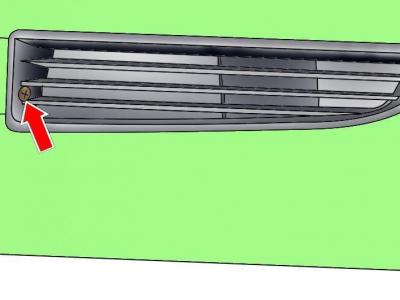
Fig. 3.2–1. Location of the screw securing the left ventilation grille
Unscrew the screw securing the left bumper ventilation grille, which also releases the right grille. Remove the grilles (Fig. 3.2–1).
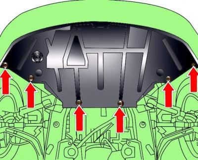
Fig. 3.2–2. Location of the engine compartment lower mudguard mounting screws
Remove the screws and remove the lower engine compartment splash guard (Fig. 3.2–2)
Remove the left and right sides of the bumper.
Cars with headlight washers
Disconnect the hose that goes through the hole in the bottom of the bumper from the washer nozzles.
Remove the front bumper.
Place a drip pan under the engine to collect the coolant.
Remove the plug at the bottom of the radiator and drain the coolant.
Loosen the mounting clamps and remove the air intake pipe connecting the air filter and the throttle body.
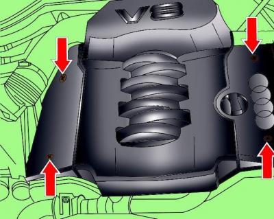
Fig. 3.2–3. Location of engine casing mounting screws
Remove the screws and remove the engine casing (Fig. 3.2–3).
Release the coolant hose clamp from the right timing belt cover.
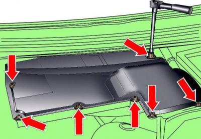
Fig. 3.2–4. Location of control unit casing mounting screws
Remove the seven screws and remove the control unit cover located in the left rear part of the engine compartment (Fig. 3.2–4).
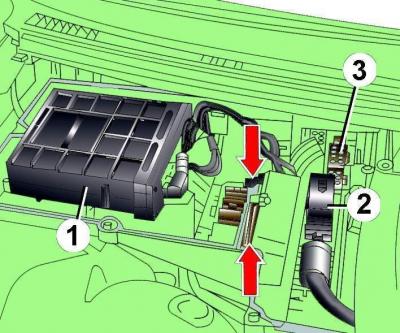
Fig. 3.1–9. Location of the engine control unit (1), drive control unit (2) and electrical connectors (3) on the engine compartment bulkhead
Disconnect the electrical connectors from engine control unit 1 (see Fig. 3.1–9) and drive control unit 2, as well as all electrical connectors on the engine compartment bulkhead.
Remove the screws securing the cruise control unit with the relay and fuse box (see Fig. 3.1–9).
Remove the seal from the top of the partition separating engine compartment and a ventilation chamber.
Label and disconnect the electrical wires from the engine.
Release the two clamps securing the flexible insulating sheath of the wires.
Unscrew the insulating braid of the wires from the engine compartment bulkhead, remove the adapter bushings from the engine compartment, remove the wires from the bulkhead and move them to the side.
Disconnect the hose from the servo motor.
Disconnect the vacuum line from the cruise control unit.
Disconnect the accelerator cable.
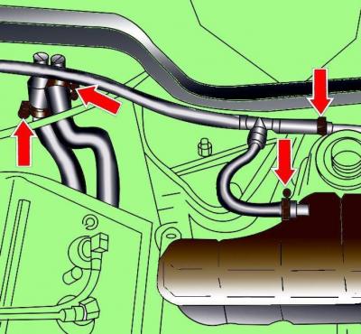
Fig. 3.1–16. Location of clamps for fastening the cooling system hoses to the expansion tank (arrows on the right) and to the heater fittings (arrows on the left) on the engine compartment bulkhead
Loosen the clamps (arrows on the left, see Fig. 3.1–16) and disconnect the cooling system hoses leading to the heater.
Disconnect the electrical connectors of the lambda sensors on the left and right sides, release the sensor wires from the clamps and move the wires to the side.
Unscrew and remove the air filter cover.
Disconnect the electrical connector from the air flow meter.
Disconnect the electrical connector from the ACF valve.
Loosen the clamps and remove the coolant pipe connecting the expansion tank and the radiator.
Remove the supply pipe to the expansion tank, having first removed the power steering fluid reservoir.
Disconnect the vacuum pipe for the intake manifold switch in front of the left headlight.
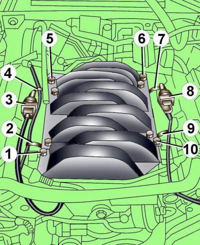
Fig. 3.2–5. Location of electrical connectors and fuel line fastening elements: 1, 5, 6, 10 – fuel line fastening bolts; 2, 4, 7, 9 – clamps; 3, 8 – electrical connectors of knock sensors
Disconnect electrical connectors 3 and 8 (Fig. 3.2–5) from the knock sensors on the left and right sides of the fuel line.
Release the four clamps 2, 4, 7 and 9 securing the electrical wires.
Disconnect the electrical connectors from the fuel injectors on the left and right sides of the engine.
Remove bolts 1, 5, 6 and 10 and carefully remove the fuel line.
Cover the open holes on the engine with a clean rag.
Remove the front bolts securing the left and right exhaust manifolds (one bolt at a time).
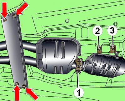
Fig. 3.2–6. Location of cross beam fastening elements and exhaust system elements: 1 – bolt connector; 2, 3 – catalytic converter mounting bolts
Remove the crossbar mounting bolts shown by the arrows in Fig. 3.2–6.
Remove the bolts of connector 1 of the exhaust system.
Remove the left catalytic converter.
Release the exhaust system clips and remove it.
Unscrew the exhaust pipes from the exhaust manifolds.
Unscrew the catalytic converter bracket with the spring and remove the catalytic converter together with the exhaust pipe.
Remove the heat shield located under the neutralizer.
Unscrew the selector lever cable heat shield from the transmission oil pan.
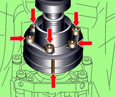
Fig. 3.2–7. Location of the mark and bolts for fastening the drive shaft flange to the gearbox
Mark the flanges of the drive shaft and gearbox, remove the bolts and disconnect the drive shaft from the gearbox (see Fig. 3.2–7).
Remove the drive shaft support mounting bolts and install the support under the shaft.
Unscrew the selector lever cable from the bracket, disconnect it from the gearbox and move it to the side.
Remove the cover covering the electrical connections.
Disconnect the starter wire at the junction box and bracket.
Unscrew the nuts securing the wires, disconnect the wires and move them to the side.
Disconnect the air duct mount from the generator.
Disconnect the pipe to the transmission oil heat exchanger.
Unscrew the coolant hose at the base of the radiator.
Disconnect the coolant temperature sensor electrical connector located above the hose.
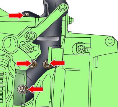
Fig. 3.2–8. Location of lower arm mounting bolts
Unscrew the lower arm mounting bolt, being careful not to lose the gaskets (Fig. 3.2–8).
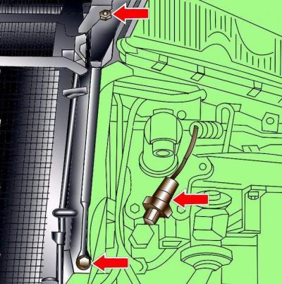
Fig. 3.2–9. Location of radiator air duct and pressure sensor connector mounting screws
Remove the radiator air duct mounting screws (Fig. 3.2–9).
Disconnect the pressure sensor electrical connector (see Fig. 3.2–9).
Disconnect the electrical connectors from the left and right headlights.
Remove the left headlight.
Disconnect the electrical connector from the catalytic converter temperature sensor and set it aside.
Unscrew the heat exchanger and move it away from the radiator.
Disconnect the radiator fan electrical connectors, release the wires from the clamps and move them to the side.
Remove the hood supports on both front fenders.
Remove the bolts located under the hood supports, while keeping the washers located under the bolts.
Unscrew the elastic elements from both sides of the bumper.
Remove the front cross member together with the radiator.
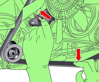
Fig. 3.2–10. Installing tool 3204 to loosen the poly V-belt tension
Loosen the tension of the poly V-belt using tool 3204 and remove the belt (Fig. 3.2–10).
Warning: Use chalk, marker or paint to mark the direction of rotation of the poly V-belt. If the poly V-belt rotates in the opposite direction during installation, it will cause damage to the belt.
Unscrew the poly V-belt pulley on the power steering pump, keeping the gasket located under the pulley as it will need to be used during installation.
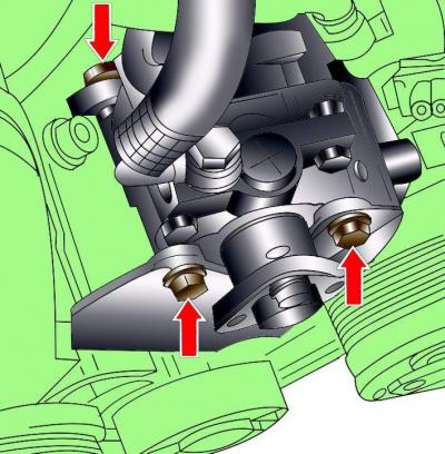
Fig. 3.2–11. Location of power steering pump mounting bolts
Unscrew the power steering pump mounting bolts and, without disconnecting the pipes, move it to the side (Fig. 3.2–11).
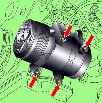
Fig. 3.2–12. Location of air conditioner compressor mounting bolts
Remove the air conditioner compressor mounting bolts and move the compressor to the side without disconnecting the pipelines from it (Fig. 3.2–12).
Save the A/C compressor guide bushings.
Install the VAG 1383 gearbox lifting device, lift the device so that the weight of the gearbox is supported by the device.
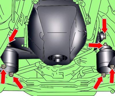
Fig. 3.2–13. Location of bolts for fastening the right and left gearbox supports
Unscrew the bolts securing the left and right gearbox supports, remove the gearbox mounting bracket and the VAG 1383 tool (Fig. 3.2–13).
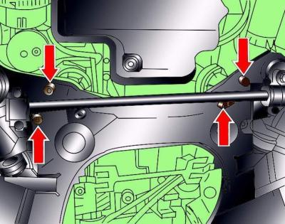
Fig. 3.1–31. Location of engine mounting bolts to the lower frame
Remove the lower engine mounting bolts to the lower frame, shown by the arrows in Fig. 3.1–31.
Place the hood vertically and secure it in this position.
Screw the VAG 3180 holders to the engine.
Make sure all electrical wires, hoses, pipes and lines are disconnected from the engine.
Attach a lifting device with a minimum lifting capacity of 500 kg to the hoist and secure it to the holders on the engine.
Carefully lift the engine away from the transmission and remove it forward from the engine compartment.
Installation
Installation is carried out in the reverse order of removal, taking into account the following.
When installing the engine, it is necessary to replace the self-locking nuts and bolts, which were tightened by turning them to a certain angle, with new ones, as well as the sealing rings and gaskets.
When installing, check for the presence of guide bushings that determine the position of the air conditioning compressor.
If the gearbox was removed from the engine, check the presence of centering bushings and the relative positions of the engine and gearbox during installation.
When connecting the engine to the gearbox, be careful not to damage the engine speed sensor.
Cars with manual transmission
Clean the drive shaft splines and remove any traces of corrosion from the clutch disc when reusing it. Lubricate the shaft splines with a thin layer of G 000 100 grease.
Check the condition of the clutch release bearing and replace it if necessary.
Using a drift, check the centering of the clutch disc.
Check the condition of the needle bearing at the flywheel end of the crankshaft. Replace the bearing if necessary.
Cars with automatic transmission
To attach the torque converter to the friction lining, it is necessary to use bolts of the original design.
Check that the torque converter is installed correctly.
Place the engine in place and rock it from side to side to ensure it is correctly positioned on the supports.
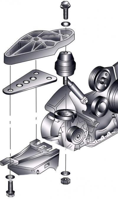
Fig. 3.2–14. Engine support elements
Install the engine support, making sure that it is not under tension (Fig. 3.2–14).
Install the poly V-belt.
Check the accelerator cable adjustment.
Fill with coolant. Do not reuse coolant if the cylinder head has been removed or the cylinder block has been replaced.
Fill the power steering system with oil and bleed the air from it.
Pour into the engine motor oil.
Make sure the exhaust system is properly mounted to the suspension and does not touch the body when rocking.
Check that the electrical connectors are connected correctly.
Connect the ground wire to the battery.
Turn on radio and enter the code into it.
Raise the power windows all the way up. Then press all the power window switches again for at least 1 second to the closed position to activate the power window control unit.
Set the time on the clock.
Before starting the engine, check the presence and level of oil in the engine.
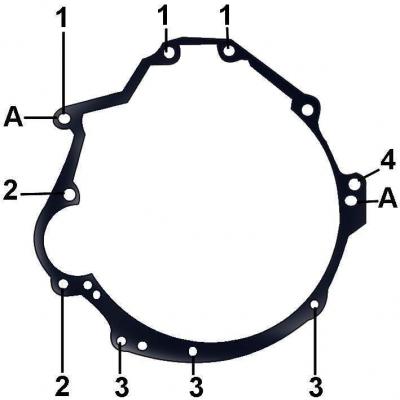
Fig. 3.2–15. Location and numbering of bolts for fastening the manual gearbox to the engine: A – location of installation of the centering sleeve