
Removal
Cars with gasoline engines
1. Drain the coolant (see the relevant chapter).
2. Disconnect the coolant hoses from the thermostat housing.
3. Unscrew the bolts (see arrows in the illustration) and remove the thermostat housing.
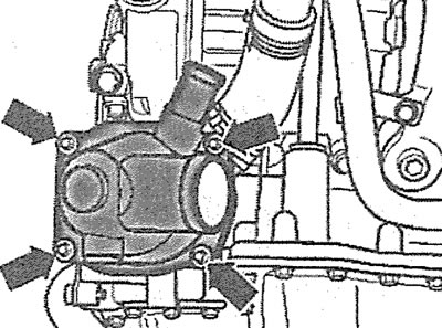
4.3. Unscrew the bolts (see arrows) and remove the thermostat housing
4. Remove the thermostat mounting bracket using a tool, part number 3265 (see arrow in illustration), and then carefully remove the thermostat from the housing.
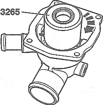
4.4. Remove the thermostat mounting bracket using a tool, part number 3265 (see arrow)
Diesel Engine Cars
5. Drain the coolant (see the relevant chapter).
6. Remove the front bumper (see the relevant chapter).
7. Set the upper front cross member to the service position.
8. Remove the accessory drive V-belt (see the relevant chapter).
9. Unscrew the bolts (see arrows in the illustration) and remove the right side of the rear timing cover.
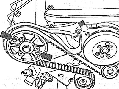
4.9. Unscrew the bolts (see arrows) and remove the right side of the rear timing cover. Diesel vehicles
10. Remove the oil filler cap.
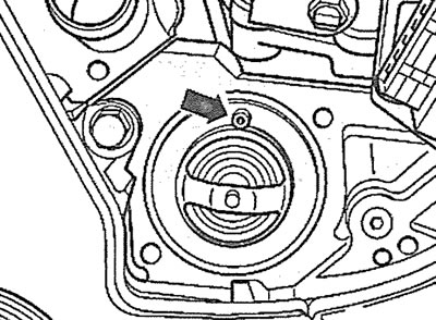
11. Turn the crankshaft in the direction of engine rotation by the central bolt securing the drive gear until the inscription "OT" appears in the hole of the oil filler neck (top dead center) on the camshaft (see illustration).
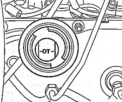
4.11 Turn the crankshaft in the direction of engine rotation by the central bolt securing the drive gear until the inscription "OT" appears in the hole of the oil filler neck (top dead center) on the camshaft. Cars with diesel engine
12. Unscrew the threaded plug on the cylinder block at approximately the level of the middle cylinder.
13. Screw in the locking pin instead of the plug, catalog number 3242 (see illustration). Make sure that the pin enters the hole in the crankshaft cheek and locks the shaft.
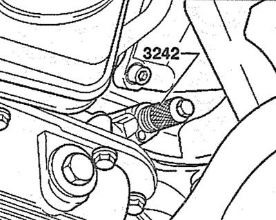
4.13. Screw in the locking pin, catalog number 3242, instead of the plug. Vehicles with a diesel engine
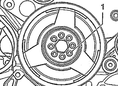
14. Unscrew bolts 1 and remove the vibration damper from the fuel injection pump gear (see illustration).
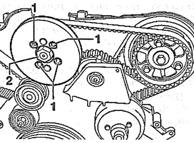
4.14. Unscrew bolts 1 and remove the vibration damper from the fuel injection pump gear. Vehicles with a diesel engine
Caution! Do not unscrew nut 2 (see illustration 4.14), as this may lead to a violation of the basic adjustment of the fuel injection pump. Subsequent adjustment of the fuel injection pump is impossible even in a workshop.
15. Mark the direction of the fuel injection pump drive toothed belt with chalk, marker or paint if it is to be reinstalled. Failure to maintain the previous toothed belt direction during its further use will result in its damage or breakage.
16. Loosen the tension of the fuel injection pump drive toothed belt by turning the roller with a socket wrench and remove the fuel injection pump drive toothed belt from the camshaft gear (see illustration).
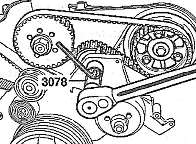
4.16. Loosen the tension of the fuel injection pump drive toothed belt. Vehicles with a diesel engine
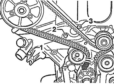
17. Unscrew the three bolts (see arrows in the illustration) and remove gear 1 of the fuel injection pump drive.
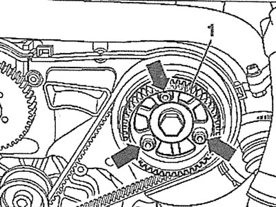
4.17. Unscrew the three bolts (see arrows) and remove gear 1 of the fuel injection pump drive. Vehicles with a diesel engine
18. Unscrew the eight bolts 1 and remove the accessory drive belt pulley from the crankshaft. The central bolt 2 secures the timing gear to the crankshaft, so there is no need to unscrew the central bolt when removing the belt pulley (see illustration).
4.18. Unscrew the eight bolts 1 and remove the accessory drive belt pulley from the crankshaft. There is no need to unscrew the central bolt 2. Vehicles with a diesel engine
19. Remove the lower part 4 of the timing gear protective cover (see illustration).
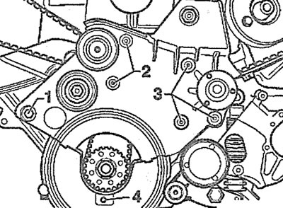
4.19. Remove the lower part 4 of the timing gear protective cover. Vehicles with a diesel engine
20. Unscrew bolts 1, 2 and 3 and remove the viscous coupling fan mounting bracket (see illustration 4.19). The guide rollers are also located on this bracket.
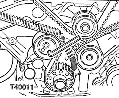
21. Slowly turn the timing belt tension roller with an 8 mm socket wrench to the right (see arrow in illustration) so that the tensioner plunger enters the housing and the holes in the housing and plunger are aligned. Insert a suitable pin, for example, a pin with catalog number T40011, into the aligned holes, thereby fixing the plunger in the tensioner housing.
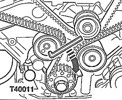
4.21. Slowly turn the timing belt tension roller to the right with an 8 mm socket wrench (see arrow) so that the tensioner plunger enters the housing and the holes on the housing and plunger are aligned. Insert the T40011 pin into the aligned holes. Vehicles with a diesel engine
Caution! The timing belt tensioner has an oil-filled plunger and therefore the plunger should be pressed into the tensioner housing slowly with a uniform force. Excessive force may damage the tension roller.
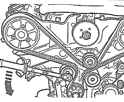
22. Feed the toothed belt on the guide roller slightly forward (see arrow in illustration).
4.22. Feed the toothed belt on the guide roller slightly forward (see arrow). Diesel Engine Cars
Caution! Do not allow the belt to slip off the guide roller, as this will require the timing belt to be completely repositioned and adjusted. Failure to do so may result in serious engine damage.
23. Disconnect the coolant hose from the thermostat housing.
24. Unscrew bolts 1-3 and remove the thermostat housing (see illustration 4.22).
25. Carefully remove the thermostat from the housing together with the sealing ring.
Installation
The thermostat is installed in the reverse order of removal.
26. Clean the contact surfaces, replace the old thermostat sealing ring with a new one.
27. Cars with gasoline engines: Install the thermostat so that the vent valve is located at the top (see arrow in illustration), bracket 2 for fastening - under trunnion 1.
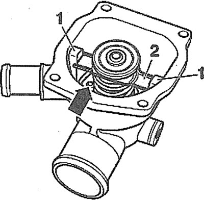
4.27. Install the thermostat so that the vent valve is located at the top (see arrow), bracket 2 fastenings - under the trunnion 1. Cars with a gasoline engine
28. Diesel vehicles: Install the thermostat so that the vent valve is located at the top (see arrow in illustration).
4.28. Install the thermostat so that the vent valve is located at the top (see arrow). Diesel Engine Cars
29. Install the new thermostat sealing ring. The working surface of the ring should face the thermostat housing.
30. Fasten the thermostat housing with bolts, having previously lubricated the threads of bolts 2 and 3 (see illustration 4.22) protective grease. The tightening torque of the thermostat housing mounting bolts is 10 Nm.
31. Move the toothed belt on the guide roller back to its original position (see arrow in illustration 4.22).
Attention! If the toothed belt has completely slipped off the roller when it is shifted, the belt must be installed and adjusted.
32. Turn the tension roller to the right with an 8 mm socket wrench (see arrow in illustration) so that it was possible to remove the T40011 pin, which secured the tensioner plunger.
4.32. Turn the tension roller to the right with an 8 mm socket wrench (see arrow)- so much so that it was possible to remove the T40011 pin, which fixed the tensioner plunger
33. Tighten the toothed belt by turning the tension roller eccentric with a torque wrench applying a force of 15 Nm counterclockwise and in this position of the eccentric tighten the roller mounting bolt (see illustration).
4.33. Tension the toothed belt by turning the tension roller eccentric with a torque wrench applying a force of 15 Nm counterclockwise
34. Install in place and secure with bolts 1-4 (see illustration 4.19) fan mounting bracket with viscous coupling. Tightening torques: bolt 1 - 45 Nm, bolt 2 - 10 Nm, bolt 3 - 22 Nm, bolt 4 - 10 Nm.
Checking the Thermostat
35. Remove the thermostat.
36. Heat the thermostat by lowering it into a container with water. The thermostat should not touch the walls of the container and should be completely immersed in water. Check the water temperature with an appropriate thermometer.
The thermostat starts to open at a water temperature of approximately +87°C; thermostat opening stops - when the water is heated to approximately +102°C. The thermostat opening stroke should be at least 8 mm.
37. Install the thermostat.