



Table of contents: Drain ↓ Refueling ↓
The coolant should only be changed after repairs to the cooling system, which required draining the coolant. Coolant is not changed as part of maintenance. If the cylinder head, cylinder head gasket, radiator, heater or engine were replaced during repairs, it is recommended to change the coolant. This is necessary so that particles of anti-corrosion protection settle on new parts made of light metals during the running-in period, thus forming a strong anti-corrosion film. The content of the anti-corrosion substance in the old coolant is no longer sufficient to form a protective layer on new parts.
Warning! Coolant is poisonous. It must not be poured out in random places. To do this, you need to find out where the nearest collection point for special means is, or hand over the coolant to a disposal point.
When refilling or replacing the coolant, use antifreeze G12 A8F (G12+), approved for use by the VW/AUDI concern. The packaging of such antifreeze indicates that it meets the technical requirements "TL VW 774F".
Concentrate G12+ can be mixed with concentrates G11 nG12.
Only G12 antifreeze, which can be recognized by its red color, should be poured into the cooling system of cars with a cooling mixture based on improved antifreeze. Attention! If a coolant that is not allowed to be used was accidentally poured into the cooling system, it should be drained and the system flushed with clean water. Let the engine run for two minutes, and then drain the water from the system. Then blow the system through the expansion tank with compressed air to completely remove water from the system. After blowing, screw the plug into the drain hole and pour in a mixture of water and G12+ antifreeze.
Attention! To replenish the coolant, including in the warm season, use a mixture of G12+ antifreeze and clean water with a low lime content. Even in summer, the proportion of antifreeze in the coolant should not be less than 40%. For this reason, when adding water to the cooling system, add antifreeze at the same time.
Attention! The antifreeze content should not exceed 60%. Otherwise, the degree of protection against freezing will decrease and the cooling effect of the liquid will deteriorate.
Antifreeze content in coolant
| Concentration | up to -25°C | up to -35°C | up to -40°C | |||
| G12+ | water | G12+ | water | G12+ | water | |
| 40% | 60% | 50% | 50% | 60% | 40% | |
Drain
1. Jack up the car and place it on jack stands.
2. Cars with parking heater. Unscrew the bolts (see arrows in the illustration) fastening the parking heater pipe to the noise-insulating shield.
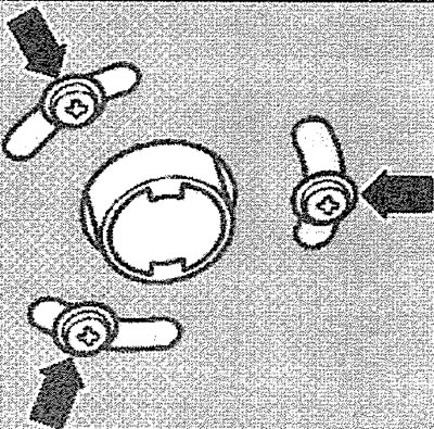
2.2. Unscrew the bolts (see arrows) fastening the parking heater pipe to the noise insulation shield. Cars with parking heater
3. Unscrew the bolts/remove the fasteners and remove the engine splash guard.
4. Remove the cap from the coolant expansion tank.
Caution! When the engine is hot, place a rag on the expansion tank cap before removing it to avoid being burned by hot coolant or steam. Remove the cap only when the coolant temperature is below +90°C.
5. Place a suitable container under the engine to collect the drained coolant.
6. Cars with gasoline engines. Unscrew the plug (see arrow in illustration) drain hole on the thermostat housing and drain the coolant.
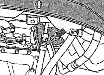
2.6. Unscrew the plug (see arrow) drain hole on the thermostat housing and drain the coolant
Attention! The cooling system of the diesel-powered vehicles discussed in this manual may have an additional drain hole, closed with a plug, or may not have one. In this case, the coolant is drained through the hole for the coolant temperature sensor.
7. Vehicles with a diesel engine, the cooling system of which has an additional drain hole. Unscrew the plug from the coolant drain hole on the outlet pipe and drain the liquid.
8. Vehicles with a diesel engine, the cooling system of which does not have an additional drain hole. Remove the bracket 1, which holds the coolant temperature sensor, remove the sensor and drain the coolant (see illustration).
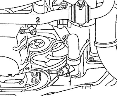
2.8. Remove the bracket 1 that holds the coolant temperature sensor, remove the sensor and drain the coolant. Vehicles with a diesel engine, the cooling system of which does not have an additional drain hole
9. Vehicles with diesel engine. Unscrew the screw plug 2 and drain the coolant (see illustration 2.8).
10. Vehicles with diesel engine. Disconnect the hose from the oil cooler by removing the clamp (see arrow in illustration) and drain the remaining coolant from the engine.
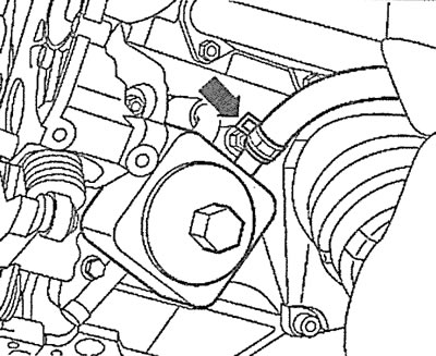
2.10. Disconnect the hose from the oil radiator by removing the mounting clamp (see arrow) and drain the remaining coolant from the engine. Diesel vehicles
Refueling
11. Screw in the plug (see arrow illustration) drain hole, replacing the old sealing ring with a new one.
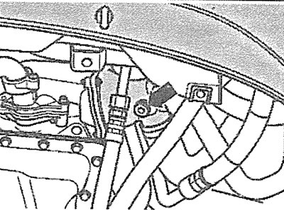
2.11. Screw in the plug (see arrow) drain hole, replacing the old sealing ring with a new one
12. Screw the VAG 1274/8 branch pipe together with the VAG 1274/10 extension onto the filler neck of the expansion tank (see illustration).
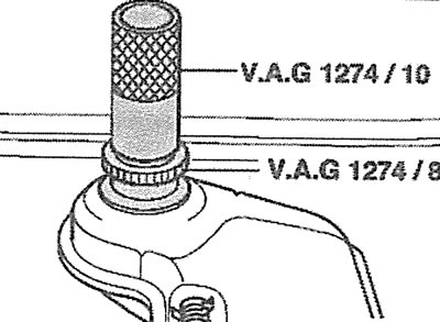
2.12. Screw the VAG 1274/8 branch pipe together with the VAG 1274/10 extension onto the filler neck of the expansion tank
This is necessary to prevent the coolant from splashing out when starting the engine and to ensure that the prescribed volume of liquid is filled. When the required level is reached, the coolant begins to flow out through the ventilation holes. If you do not have a pipe, you can make one yourself. You can also unscrew the expansion tank and, without disconnecting the hoses, raise it by 10 cm, securing it with wire.
13. Loosen the clamp on the heater return hose and move the hose so that the ventilation hole (see arrow in illustration) the branch pipe was not covered with a hose.
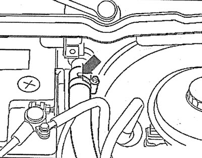
2.13. Loosen the clamp on the heater return hose and move the hose so that the ventilation hole (see arrow) the branch pipe was not closed with a hose
14. Fill with coolant until it starts to flow out of the vent on the heater return hose. Then slide the return hose onto the fitting and secure with a clamp.
15. Cars with gasoline engines. Unscrew the plug (see arrow in illustration) vent on the left auxiliary radiator hose to allow coolant to flow out. When coolant starts flowing out of the hole without air bubbles, screw in and tighten the vent plug by hand.
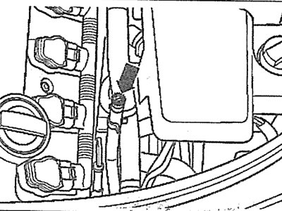
2.15. Unscrew the plug (see arrow) vent on the left auxiliary radiator hose to allow coolant to drain. Gasoline-powered vehicles
16. Cars with gasoline engines. Unscrew the plug (see arrow in illustration) vent on the right auxiliary radiator hose to allow coolant to flow out. When coolant starts flowing out of the hole without air bubbles, screw in and tighten the vent plug by hand.
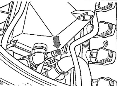
2.16. Unscrew the plug (see arrow) vent on the right auxiliary radiator hose to allow coolant to drain. Gasoline-powered vehicles
17. Install the expansion tank back in place if it was removed and secure it with bolts.
18. Remove the ventilation device (see illustration 2.12) and screw the cap onto the neck of the expansion tank.
19 Turn on the interior heater or air conditioner by moving the switch to the heating position.
20. Start the engine and let it idle until the radiator warms up near the pipe where the lower hose connects.
21. Turn off the engine.
22. Check the coolant level and top it up if necessary. When the engine is warm, the coolant level should be above the "MAX" mark on the expansion tank, and when the engine is cold, between the "MIN" and "MAX" marks on the expansion tank (see illustration).
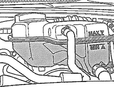
2.22. When the engine is warm, the coolant level should be above the "MAX" mark on the expansion tank, and when the engine is cold, between the "MIN" and "MAX" marks