
For additional cooling of the liquid, a radiator blower is installed. At low temperatures, a viscous coupling on the fan rotor hub reduces its rotation speed. With an increase in the coolant temperature to a certain value, the coupling turns on the fan and it operates at an increased speed.
Depending on the configuration, for example, an air conditioner, an electric radiator fan is additionally installed. This fan is controlled by a two-stage thermal relay, which is screwed into the radiator at the bottom left or is located in the lower coolant circulation hose. When the coolant reaches a temperature of +92-97°C, the thermal relay turns on the electric fan, which operates at the first rotation stage. With an increase in the coolant temperature to +99-105°C, the electric fan operates at full power.
Since the electric radiator fan does not operate continuously and the coolant circulation is regulated by a thermostat, the engine warms up to operating temperature faster. Fuel consumption is reduced.
Caution! The electric fan may automatically turn on when the ignition is off due to heat accumulating in the engine compartment. It is recommended to disconnect the electric fan power plug before performing work in the engine compartment, especially near the radiator fan.
Caution! When working on the cooling system, do not allow coolant to come into contact with the timing belt. Ethylene glycol, which is part of the coolant, can damage the base of the belt so much that it will break after a while. This, in turn, is fraught with serious damage to the engine.
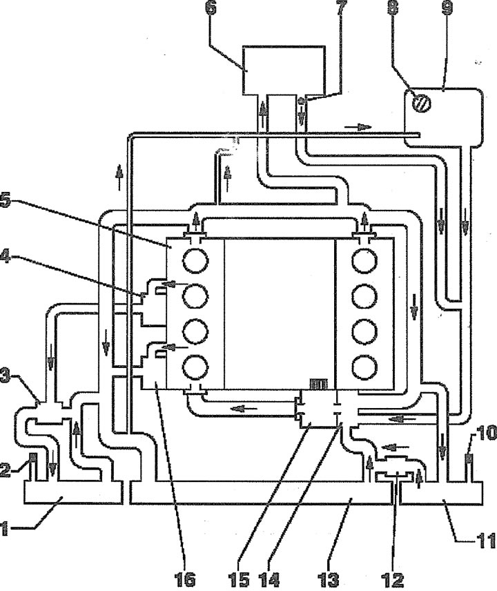
1.0. Coolant circulation. Cars with gasoline engines:
1 - right additional radiator
2 - Ventilation hole plug
3 - thermostat
4 - oil radiator
5 - cylinder head
6 - heater radiator
7 - ventilation hole
8 - coolant expansion tank cap
9 - coolant expansion tank
10 - Ventilation hole plug
11 - left additional radiator
12 - check valve
13 - radiator
14 - thermostat
15 - water pump
16 - generator
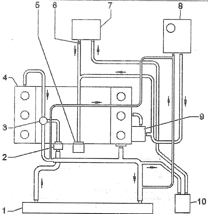
1.0a. Coolant circulation. Vehicles with diesel engine and parking heater:
1 - radiator
2 - thermostat
3 - coolant temperature sensor
4 - cylinder head
5 - water pump
6 - ventilation hole
7 - heater radiator
8 - coolant expansion tank
9 - oil radiator
10 - parking heater
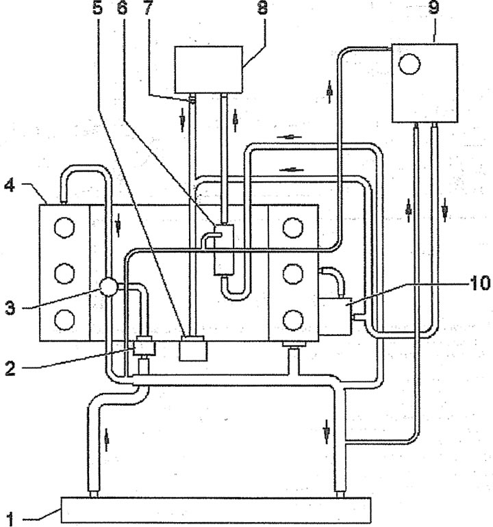
1.0b. Coolant circulation. Vehicles with a diesel engine and a radiator for cooling exhaust gases diverted for afterburning:
1 - radiator
2 - thermostat
3 - coolant temperature sensor
4 - cylinder head
5 - water pump
6 - radiator for cooling exhaust gases diverted for afterburning
7 - ventilation hole
8 - heater radiator
9 - coolant expansion tank
10 - oil radiator