
Table of contents: 3.2 TDI 1st generation engines:… ↓ 3.2 TDI SCR engines ↓ Engines 3.2 TDI 2nd generation ↓ 4.2 TDI models ↓
3.2 TDI 1st generation engines: sensors G62 and G83
1. Wait until the engine cools down.
2. Open and close the expansion tank cap to relieve coolant pressure.
3. Remove the upper engine cover (see Section 19 of Chapter 1).
4. To remove the radiator outlet temperature sensor "G83", disconnect the connector (2 in illustration 4.8 Chapter 2) sensor, pull out the retaining clip and remove the sensor.
5. To remove the "G62" ECT sensor, remove the air hose (see illustration 15.6 Chapter 2), disconnect the connector (1 in the illustration), pull out the retaining clip (2) and remove the sensor.
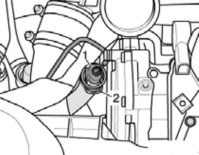
7.5. Connector (1) of sensor G63 of 3.2 l TDI engines of the 1st generation.
6. Installation is carried out in reverse order. Use a new O-ring. To avoid unnecessary coolant loss, install a new sensor immediately. Finally, adjust the coolant level.
3.2 TDI SCR engines
7. Details of the installation of the coolant lines are shown in the illustrations.
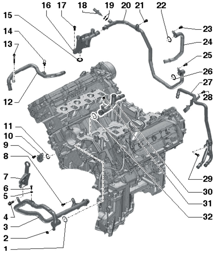
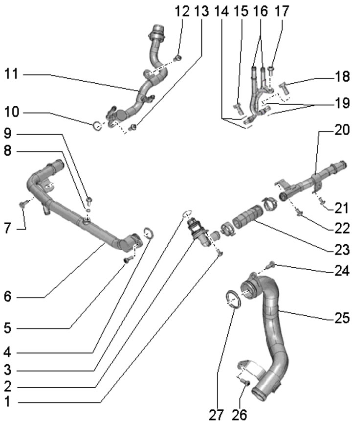
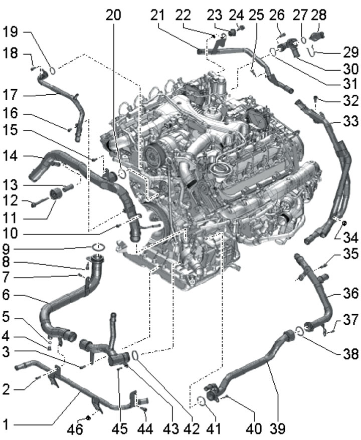
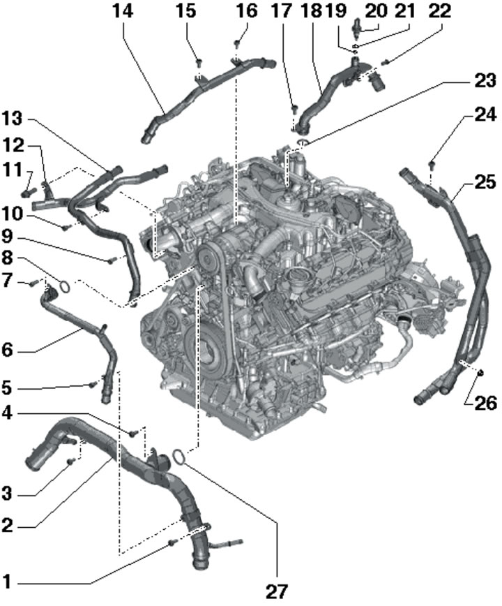
7.7a. Coolant line installation details for 3.2 TDI SCR engines (part 1 of 2):
1, 11, 15, 19, 22, 32 - O-ring, subject to replacement;
2, 17, 31 - Nut, 9 Nm;
3 - Right coolant pipe;
4 - Bolt, 23 Nm;
5 - Gasket, subject to replacement;
6 - Bolt in the bleed hole, 9 Nm;
7 - Engine lifting eye;
8, 9, 21, 23, 25, 28, 29 - Bolt, 9 Nm;
10, 16 - Connection;
12 - Right upper coolant pipe;
13 - Bolt;
14 - Upper engine casing mounting pin;
18 - ECT sensor "G62", 2 Nm;
20 - Rear coolant pipe;
24 - Rear left coolant pipe on the additional EGR radiator;
27 - Rear left coolant pipe on AT;
30 - Upper coolant pipe.
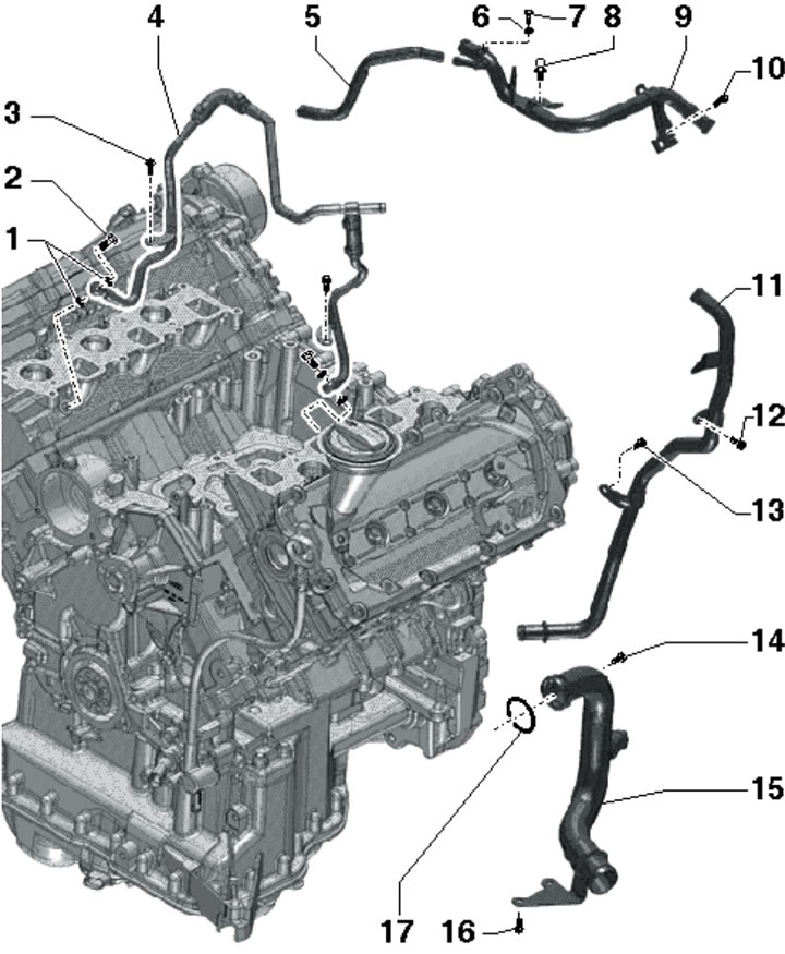
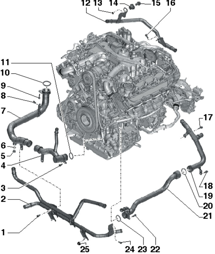
7.7b. Coolant line installation details for 3.2 TDI SCR engines (part 2 of 2):
1, 6 - Gasket, subject to replacement;
2 - Hollow bolt, 15.5 Nm;
3, 10, 12-14, 16 - Bolt, 9 Nm;
4 - Coolant pipe, to cylinder heads;
5 - Coolant hose, from EGR thermostat;
7 - Bolt in the bleed hole, 9 Nm;
8 - Upper engine casing mounting pin;
9 - Upper left coolant pipe;
11 - Rear left coolant pipe;
15 - Left coolant pipe;
17 - Sealing ring, must be replaced.
The following describes the removal/installation of sensors G62 and G83.
8. Follow the steps described in paragraphs 1-3.
9. Removal of the coolant temperature sensor at the radiator outlet (G83) on models up to 05.2010 is carried out in the same way as on 3.2 TDI engines of the 1st generation (see paragraph 4). On models from 06.2010, disconnect the connector (3 in illustration 15.1 of Chapter 2), pull out the lock (2) and pull out the G83 sensor.
10. To remove the "G62" ECT sensor, remove the air hose (see illustration 15.6 Chapter 2), disconnect the connector (1 in the illustration) and remove the sensor.
7.10. ECT sensor connector for 3.2 TDI SCR engines.
11. Installation is carried out in reverse order. Use a new O-ring. To avoid unnecessary coolant loss, install a new sensor immediately. Finally, adjust the coolant level.
Engines 3.2 TDI 2nd generation
12. The details of the installation of the coolant lines are shown in the illustrations.
7.12a. Coolant lines on 3.2 TDI 2nd generation engines:
1, 5, 7, 12, 13, 17, 21, 22, 24, 26 - Bolt, 9 Nm;
2 - Non-return valve, one on each bank of cylinders, under the engine mount;
3, 4, 10, 27 - O-ring, subject to replacement;
6 - Front coolant pipe;
8, 9 - Not used;
11 - Upper coolant pipe;
14, 19 - Gaskets, subject to replacement;
15, 18 - Hollow bolt, 12 Nm;
16 - Coolant pipes for the left cylinder head;
20 - Left coolant pipe;
23 - Coolant hose;
25 - Lower left coolant pipe.
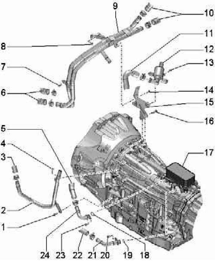
7.12b. Coolant lines on the AT side of 2nd generation 3.2 TDI engines:
1, 4, 7, 8, 13, 14 - Bolt, 9 Nm;
2 - Left coolant pipe on the AT;
3, 5, 6, 10, 11 - Coolant hoses;
9 - Upper left coolant pipes on AT;
12 - Valve "N488" for supplying coolant to the AT;
15 - Valve bracket 12;
16 - Bolt, 23 Nm;
17 - ATF radiator;
18, 19 - Sealing ring, subject to replacement;
20, 23 - Bolt;
21, 24 - Coolant pipe;
22 - Coolant hose.
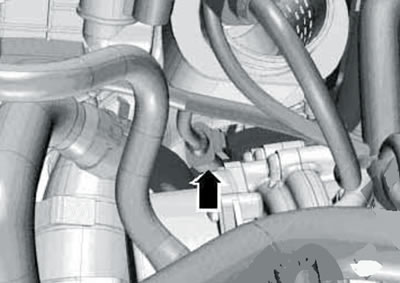
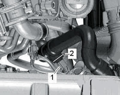
13. To remove the non-return valves, it is necessary to drain the coolant (see Section 2), remove the engine supports and crossmember, as well as the corresponding support bracket (see chapter 2). Remove the bolt (see illustration) and remove the non-return valve.
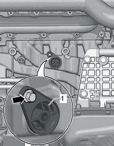
7.13. Non-return valve bolt.
14. The coolant shut-off valve installation details are shown in the illustration. Removal of the valve is possible after removing the EGR radiator (see Chapter 4).
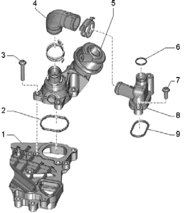
7.14. Coolant shut-off valve installation details:
1 - Mounting plate for oil cooler and fuel shut-off valve (see Chapter 2);
2, 9 - Gasket, subject to replacement;
3, 7 - Bolt, 9 Nm;
4 - Coolant hose;
5 - Coolant shut-off valve;
6 - Sealing ring, must be replaced;
8 - Connection of the coolant hose and pipe.
15. The details of sensor installation are shown in the illustration.
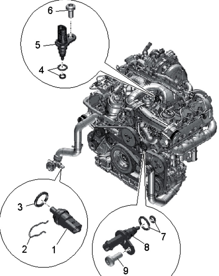
7.15. Details of installation of engine cooling system sensors:
1 - Sensor G83 coolant temperature at the radiator outlet;
2 - Retainer;
3, 4, 7 - Sealing rings, subject to replacement;
5 - ECT Sensor "G62" 6.9 Bolt, 9 Nm;
8 - Temperature sensor "G694" for regulating engine temperature.
To remove the sensors, first of all, you should follow the steps described in paragraphs 1-3.
16. To remove the G694 sensor, remove the drive belt and its idler roller (see Chapter 2), and then disconnect the connector (1 in the illustration) and unscrew the bolt (2).
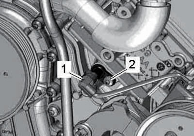
7.16. Bolt (1) for fastening the G694 sensor (2).
17. To remove the G83 sensor, disconnect its connector (2 in illustration 4.8 Chapter 2) and pull out its retainer.
18. To remove the G62 sensor, disconnect the connector (2 in the illustration) and unscrew the bolt (1).
7.18. Bolt (1) and connector (2) of the ECT sensor "G62".
4.2 TDI models
19. The details of the installation of the coolant lines are shown in the illustrations.
7.19a. Coolant lines for 4.2 TDI engine (BTR):
1 - Coolant pipe going to the additional radiator;
2, 3, 7, 8, 10, 15, 16, 18, 25, 26, 32, 34, 35, 37, 40, 44, 45 - Bolt, 9 Nm;
4 - Drain plug, 15 Nm;
5 - Gasket, subject to replacement;
6 - Right coolant pipe;
9, 19, 20, 27, 31, 38, 41, 42 - Sealing ring, subject to replacement;
11 - Right intermediate roller of the drive belt;
12, 24 - Bolt;
13, 23 - Spacer sleeve;
14 - Central front coolant pipe;
17 - Front upper coolant pipe;
21 - Rear right coolant pipe;
22, 34 - Nut, 9 Nm;
28 - ECT sensor "G62";
29 - Retainer;
30 - Connection;
33 - Rear left coolant pipes (only on models with 4-zone climate control system);
36 - Rear left coolant pipe;
39 - Left coolant pipe;
43 - Front lower coolant pipe;
46 - Nut, 9 Nm, 2 pcs.
7.19b. Coolant lines of the 4.2 TDI engine (CCFA/CCFC, Part 1 of 2):
1, 4, 5, 7, 9, 10, 15-17, 22, 24, 25 - Bolt, 9 Nm;
2 - Front central coolant pipe;
3 - Bolt, 22 Nm;
6 - Front upper coolant pipe;
8, 23, 28 - O-ring, subject to replacement;
11 - Bolt, 23 Nm;
12 - Right coolant pipe for EGR;
13 - Left coolant pipe for EGR;
14 - Upper coolant pipe for EGR;
18 - Upper coolant pipe;
19 - Small sealing ring, must be replaced;
20 - ECT sensor "G62", 2 Nm;
21 - Large sealing ring, must be replaced;
26 - Rear left coolant pipes, only on models with 4-zone climate control system;
27 - Nut, 9 Nm.
7.19 p. Coolant lines of the 4.2 TDI engine (CCFA/CCFC, Part 2 of 2):
1, 3, 8, 9, 15-18, 22, 24, 25 - Bolt, 9 Nm;
2 - Front lower coolant pipes;
4 - Front lower coolant pipe;
5 - Drain plug, 15 Nm;
6 - Gasket, subject to replacement;
7 - Right coolant pipe;
10, 11, 20, 23 - O-ring, subject to replacement;
12 - Rear right coolant pipe;
13 - Nut, 9 Nm;
14 - Spacer sleeve;
19 - Rear left coolant pipe;
21 - Left coolant pipe.
The following describes the removal/installation of the G83 coolant temperature sensor at the radiator outlet.
20. Wait until the engine bearing cools down. Remove the upper engine cover (see Section 19 of Chapter 1).
21. Remove and install the expansion tank cap to relieve pressure in the cooling system.
22. Loosen the clamps (1 in illustration 35.19 Chapter 2) and remove the air hose.
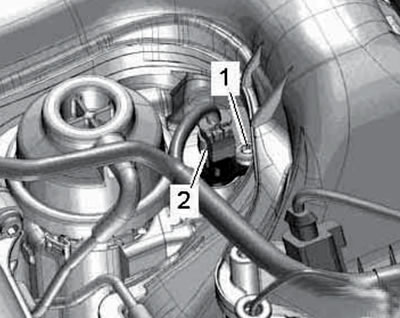
23. Disconnect the connector (1 in the illustration) sensor G83, pull out the retainer (2) and remove the sensor.
7.23. Connector and retainer of the G83 sensor.
To avoid unnecessary coolant loss, install a new sensor immediately.
24. Installation is carried out in reverse order. Use a new O-ring. Finally, adjust the coolant level.
(The original article is located on the online resource «audimanual.ru»)