
Cooling circuit of the engine with a turbocharger 1.8 l
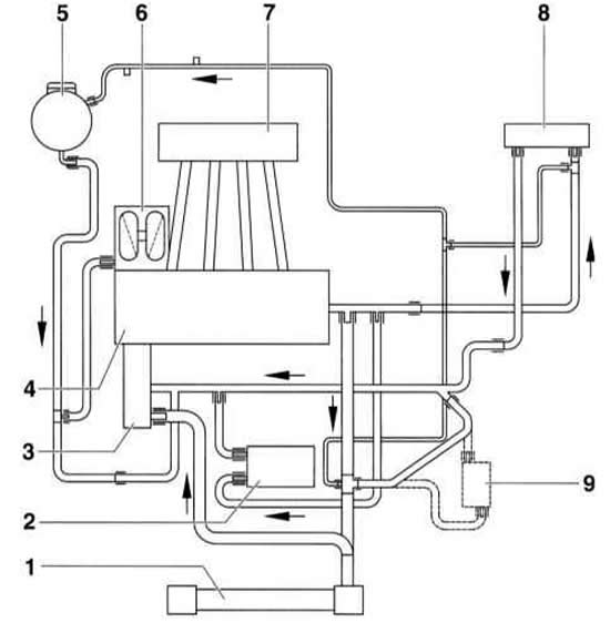
- 1 radiator
- 2 oil radiator
- 3 Coolant pump/thermostat
- 4 cylinder head/side
- 5 expansion tank
- 6 turbocharger
- 7 intake manifold
- 8 heater radiator
- 9 ATF radiator. Only for models with automatic transmission
The cooling circuit of other engines is built on the same principle.
Until the engine is warmed up, the coolant circulates only in the cylinder head and block and in the heat exchanger of the interior heater. As the coolant temperature increases, the thermostat opens the large cooling circuit. The coolant is directed through the radiator by a constantly running pump. The liquid passes through the radiator from top to bottom and is cooled by the air passing through it.
To improve cooling efficiency, the system is equipped with a temperature-controlled fan.
Control is carried out by a two-stage thermal switch screwed into the left side of the radiator expansion tank. At a coolant temperature of +92° to 97°C, the thermal switch turns on the first stage of the fan (half of the full number of revolutions). If the coolant temperature rises from +99° to 105°C, the fan switches on at full speed.
Due to the fact that the fan does not operate constantly, as well as the presence of thermostatic regulation of the coolant flow, the engine operating temperature is reached faster and fuel consumption is reduced.
Warning: The electric fan may turn on when the ignition is off. Due to heat stagnation in the engine compartment, the fan may turn on multiple times. Solution: Disconnect the radiator fan connector.