
Table of contents: Removal and installation the EGR… ↓ Removal and installation the vacuum… ↓
1. The installation details of the EGR system components using 2.0 DOHC diesel engines as an example are shown in the illustration.
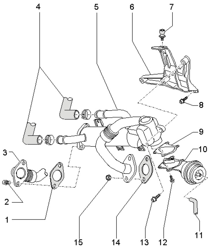
18.1. EGR system installation details 1. Gasket, subject to replacement; 2. Bolt, 25 Nm; 3. EGR system connecting pipe; 4. Coolant hoses; 5. EGR radiator; 6. Bracket; 7. Engine top cover retainer; 8. Bolt, 9 Nm; 9. Gasket; 10. Vacuum block; 11. Vacuum hose from radiator changeover valve 5; 12/13. Bolt, 7/9 Nm; 14. Gasket, subject to replacement; 15. Nut, 25 Nm, subject to replacement
Removal and installation the EGR radiator
2. Remove the decorative engine cover.
3. Drain the coolant (see Chapter 3).
4. Remove the air cleaner air intake (see Section 16 Chapter 1).
5. Disconnect the connector (1 in illustration 17.33 Chapter 2) MAF sensor, loosen the clamp (2) and remove the air hose. Move the wiring away from the air cleaner housing and remove it.
6. Disconnect the vacuum hose (3 in illustration 47.5 Chapter 2) from the vacuum block and coolant hoses (1 and 2) from the EGR radiator.
7. Remove the bolts (1 in illustration 47.6 Chapter 2) and nuts (2), unscrew the bolts (arrows) and remove the EGR radiator.
8. Installation is carried out in the reverse order of dismantling the components.
Removal and installation the vacuum block
9. Remove the decorative engine cover.
10. Remove the air cleaner air intake (see Section 16 Chapter 1).
11. Disconnect the connector (1 in illustration 17.33 Chapter 2) MAF sensor, loosen the clamp (2) and remove the air hose. Move the wiring away from the air cleaner housing and remove it.
12. Disconnect the vacuum hose (3 in illustration 47.5 Chapter 2) from the vacuum block.
13. Remove the bolts (1 in illustration 47.6 Chapter 2) and nuts (2), unscrew the bolts (arrows) and move the EGR radiator to the side with the coolant hoses connected.
14. Remove the bolts (1-4 in the illustration) and remove the vacuum block with the gasket.
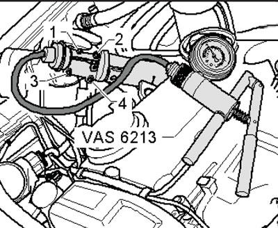
18.14. Fastening the vacuum block
Note: Please ignore the VAS6213 device shown in the illustration.
15. Installation is carried out in the reverse order of dismantling the components. Before installation, use a hand vacuum pump to set the switching flap (1) to the position shown in the illustration.
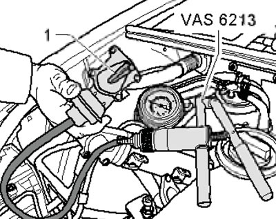
18.15. Setting position of the switching flap