
Schematic 2-12. Cooling system, radiator fan relay, radiator fan relay 2, coolant pressure sensor
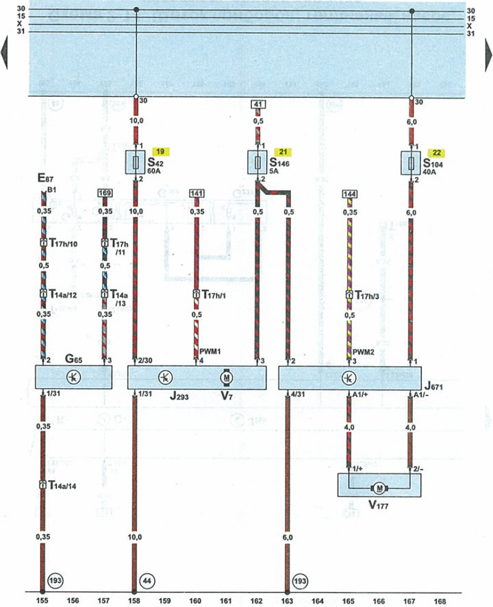
| E87 | heater/air conditioner control unit |
| G65 | refrigerant pressure sensor |
| J293 | radiator fan relay in the front part of the engine compartment on the left |
| J671 | relay 2 radiator fan |
| S42 | radiator blowout fan fuse |
| S104 | radiator blowout fan fuse (2nd speed rotation) |
| S146 | radiator blowout fan fuse (operating mode after engine stop) |
| T14a | 14-pin black plug in the front left side of the engine compartment |
| T17h | 17-pin brown connector on the left side of the A-pillar |
| V7 | radiator blower fan |
| V177 | fan 2 radiator blower |
| 44 | ground point (-) on the left side of the front pillar below |
| 193 | connection 1 to "ground" (-) in the radiator fan wiring harness |