
Scheme 2.11. Engine control unit, CAN-Bus data exchange bus, brake booster relay, brake vacuum pump
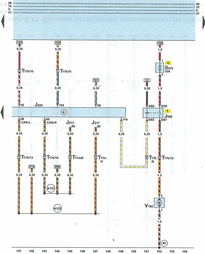
| J217 | automatic transmission control unit |
| J220 | engine control unit |
| J569 | brake booster relay |
| S279 | ABS modulator pump relay fuse |
| T17k | 17-pin red connector on the fuse/relay box under the fairing |
| T17m | 17-pin blue connector on the right side of the A-pillar |
| V192 | brake drive vacuum pump |
| 85 | connection 1 to ground (-) in the engine compartment wiring harness |
| A121 | high-Bus data exchange wire in the instrument panel wiring harness |
| A122 | low-Bus data exchange wire in the instrument panel wiring harness |
| • | cAN-Bus data exchange bus |
| * | only cars for countries with hot climates |
(The original publication in its entirety is posted on the website: AudiManual.ru)